
Computer Science
Totalisators: Large-Scale Machines
Given that we have a summary of the first Julius totalisator and that the story of the large totes has been outlined in the overview this account will mainly concern the improvements that were made to the large machines over the years. There are also some more details on the machines that still survive.
Even before the first machine at Ellerslie was operating Julius wanted to make improvements, particularly using electricity. These were made for the next machine at Perth in 1915 but we have no details. However, electricity was essential to the new machines installed in 1918, such as that at Randwick in Sydney. There were two main uses of electricity, electrical connection of ticket machines and power to drive the adders and other components.
The first post-war machines were provided with ticket issuing machines (TIMs) that, after registering each bet, would print the ticket from blank paper rolls. The connection at this stage was a one for one replacement of the steel wires in the Ellerslie machine. Each TIM had its own escapement on each horse adder but the escapement was operated by a solenoid. The solenoid was itself activated by the TIM completing an electrical circuit - there being one such connecting wire from each TIM to every horse adder. It appears that the adders at Randwick were large like those at Ellerslie. Although they could be connected remotely, the number of TIMS was limited by what could be accommodated on one shaft adder. Thus, in order to accommodate the crowds, the installation at Randwick had three machines at different places around the course - the machines operating independently.
It is likely that one important innovation was present early in the post war period. Rather than adding the horse totals at a final stage to form the grand total, the grand total addition was performed by another horse adder, the same as the others. The circuit from TIM to escapement solenoid was extended to a common input to the solenoid at the same position on the grand total adder. The speed of the grand total adder didn't really provide a limitation as, in the limit, the adder for the hot-favourite horse operated at the same speed. This way of dealing with the grand total remained a feature of the ATL machines.
The other new use of electricity was providing power to drive the machine. The new TIMs were presumably power driven, but the biggest change was doing away with having to raise weights to drive the machine. In 1915 Julius patented the idea of having the weights raised automatically - perhaps this was used in Perth. The method chosen eventually was to use a central powerful electric motor to drive shafts that in turn impelled the adders by means of slipping clutches. This was certainly in place by the early twenties.
Machines for printing and issuing tickets are a crucial part of any totalisator mechanisation. Julius had designed such a machine even before the first machine at Ellerslie was constructed (it could pull a unique wire for each horse) though it was never used. And nowadays with computers doing the work the totalisator "hardware' industry is devoted largely to the design and provision of TIMs. TIMs are only of peripheral interest here so we will have only the essentials.
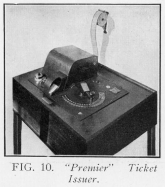
As well as printing the ticket the TIM has to signal the central machinery that the bet has been made. At the start, if there were, say, 24 horses maximum this was just completing one of 24 circuits to one of the escapements in the adder for the that horse. Not much is known about the earliest TIMs, they might have used a keyboard for selecting the horse, but ATL soon settled on an approach that was retained until the 1950s, where there was a swivel-arm that could be depressed into one of (say) 24 holes. The TIMs had interlocks to prevent the printing of the ticket until the bet was registered and also to prevent the registering of a new bet until the previous ticket was printed. One of the machines used in the 1920s is shown in the picture alongside taken from an ATL brochure of 1930 - a diagram (from Peter Collier) of the same or similar TIM is here.
The series of ticket machines that were made by ATL were given "J" designations, from J1 onwards. Most of the surviving ticket machines used with the electromechanical machines are J8s like the one alongside. Over the years there were many improvements made to the TIMs. Security, foiling counterfeiters, was an important issue - the later TIMs could print codewords and small "logos" as well as the horse number. Initially the TIMs could record bets of only one value but were later extended to make multiple unit bets for the one ticket and so cover a range of values. Later machines also allowed multiple types of bets to be recorded, particularly both win and place.
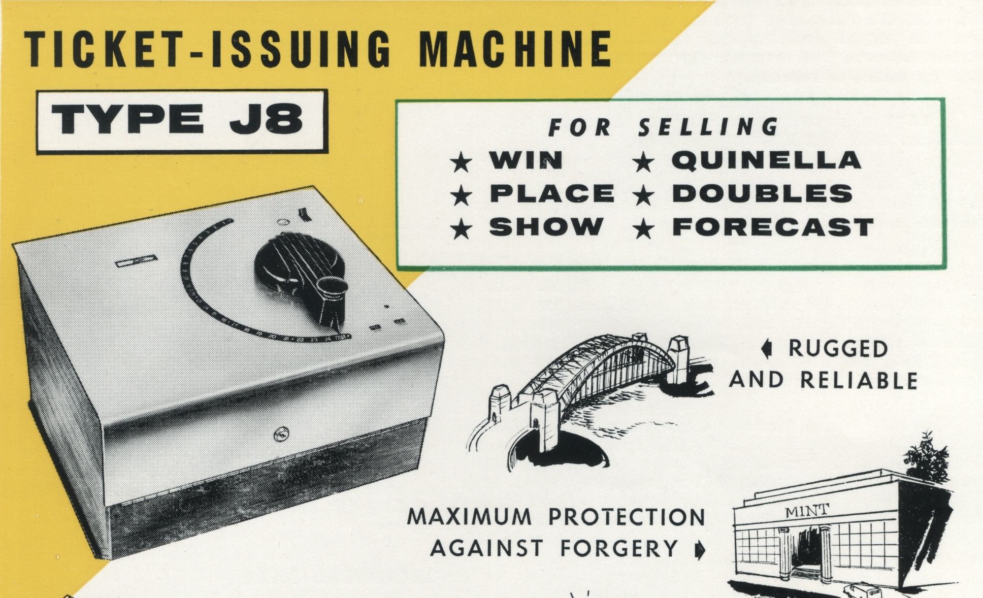
Portion of an ATL TIM Advertising Brochure
The Power House Museum has a small archive concerning Henry Roy Setright. According to the archive description he was an Australian engineer involved in the development of the automatic totalisator machine with Sir George Julius and was responsible for ATL's early ticket issuing machines. He established the company The Premier Automatic Ticket Issuers Limited in 1917. In 1922 he sold his Australian rights in the totalisator and ticketing machines to Automatic Totalisators Limited. He later operated from Europe and was associated with the Universal Automatic Totalisator Company that sold totalisators and ticket machines in Great Britain and France and had a factory in France from 1928. (A Universal machine was used by the company Portable Electric Totalisators in Palmerston North - this was later moved to Invercargill.)
The main problem with the very early Julius machines was that with large numbers of ticket issuers the adders grew too large and cumbersome. From the start the machines were designed to accommodate a rate of ticket issuing that was unrealistically high - in practice all ticket issuers had delays of many seconds between issuing successive tickets (dealing with change etc.) By 1920 Julius had announced that he had a solution to this problem which took advantage of the realistic rate of ticket issue to allow multiple TIMs to multiplex one escapement and its solenoid. Once introduced, this remained a feature of Julius machine in the electomechanical era.
Contemporaneous with the totalisator a much much larger industry was being developed, that of automatic telephony. Telephony produced its own technology of switching that had extreme requirements for reliability and involved production of components benefiting from economies of scale. Totalisators and automatic exchanges have related problems to solve so it was natural for totalisator designers to draw on what telephony provided. This was not so clear with ATL technology to start with because it was developed early but late entrants in the totalisator business were reliant on telephony switching components (by the 1950s ATL also made much use of telephone switching equipment.)
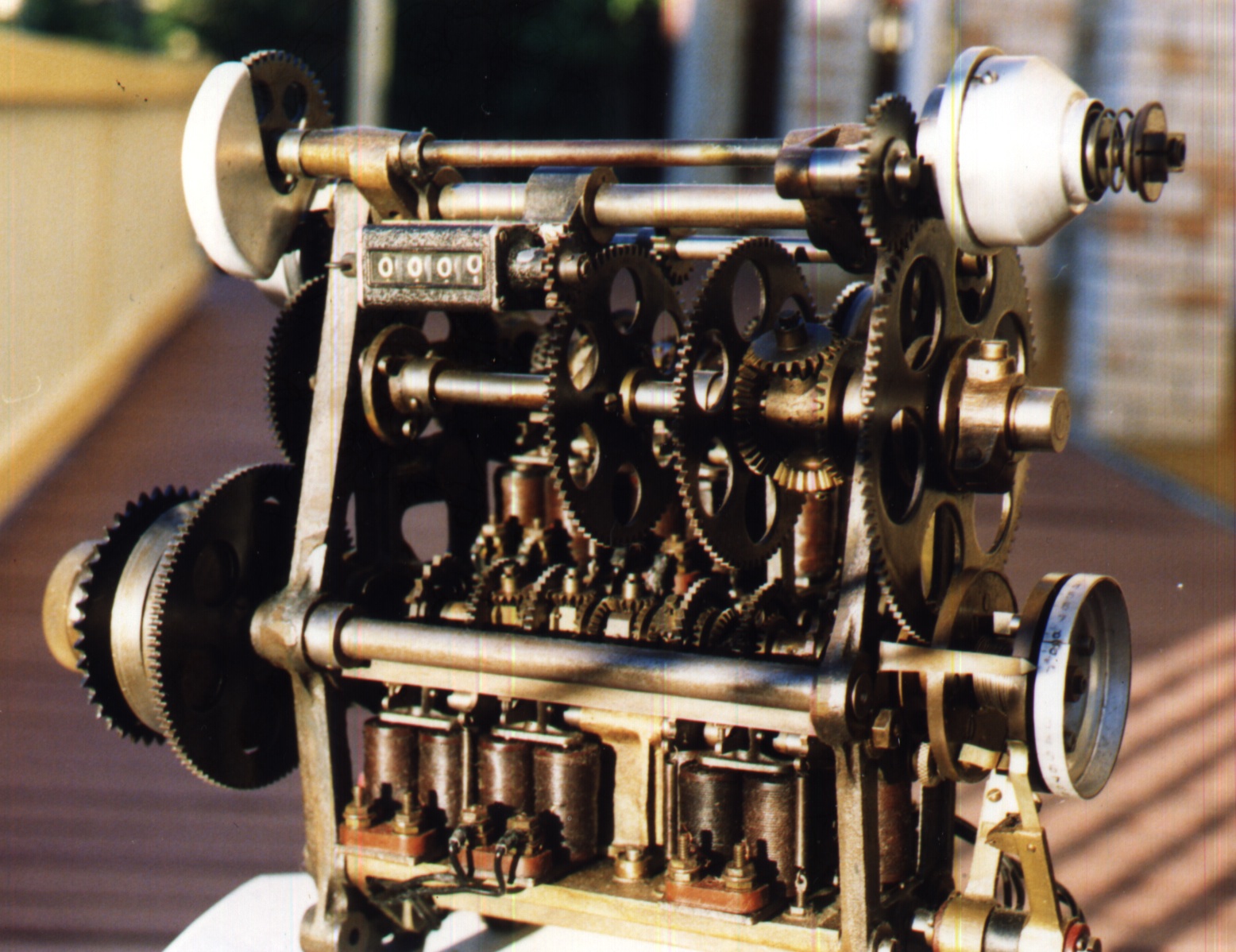
Scanner, 1935
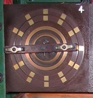
The main device introduced for multiplexing escapements was their scanner. This was a rotary switch driven by by a motor that completed the circuit to each TIM in a group in turn, registering any bet quickly. Perhaps the best way to understand this is to think of the scanner as moving slowly, closing one TIM circuit, giving it adequate time to operate, then moving to the next etc. (The scanner here, from Riccarton, c. 1935, was actually a "two in one" version for a win/place machine - we do not have an image of the earlier scanners with just one ring of contacts.)
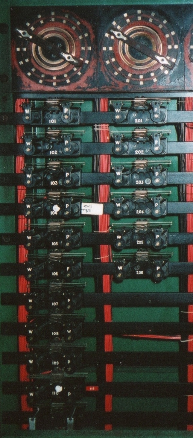
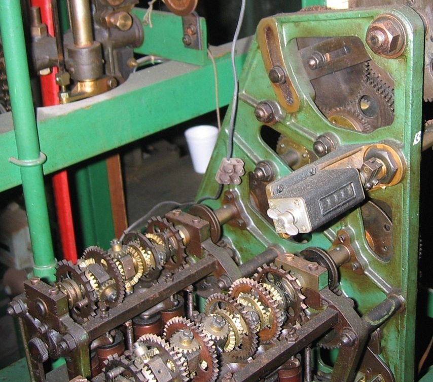
Scanner and Relays, 1946
Although that describes the function it would be inadequate because of the time taken to service a TIM which the scanner had just passed. To solve this problem the designers of the scanner controller drew on the technology and techniques of relays from telephony. A relay is a switch operated by current flowing through a solenoid. However, relay switches are not simple - the one relay may operate many switches, opening some and closing others at the same time. Relays can even open then close the one switch. Because of their complexity there was never developed a general design methodology like that used for electronic logic circuits. Rather, designers drew on patterns of components that had been shown in practice to be useful. So, rather than try to explain how the scanner made use of relays we will just "kick for touch" and describe what they did. (The image here is scanners and relays for a 1946 machine at Awapuni.)
In fact the scanners rotated quite quickly, perhaps at 90 rpm. A TIM bidding to register a bet would close its circuit for a particular horse and the selection arm would be held depressed by a catch. When the scanner closed the circuit for trying to register a bet, a relay was activated unique for that TIM that provided power for the circuit and turned off the scanner (which continued rotating at the same speed but having no affect.) The completed circuit registered the bet by activating the solenoid on the appropriate horse adder and the solenoid on the grand total adder. It also operated another solenoid in the TIM that released the catch holding the TIM selection arm down. The arm would then rise and break the circuit, which would cause the relay for that TIM to switch back, eliminating the power source for the TIM circuit and turning the scanner power back on. The scanner would then continue and select the next TIM bidding to register a bet.
So with a scanner it was possible to have 8, 10, 16, or more TIMs share one escapement. It was also possible for the TIMs attached to the one scanner share the circuit lines for each horse. Thus the amount of equipment and wiring needed for smaller machines was greatly reduced and it also became possible to design machines that could handle the largest racetracks.
The way the scanner operates brings to mind control of "multi-drop" lines to terminals in early computers. However, although the speed of the scanner was divorced from the speed of the registration of a bet and reaction of the TIM, there was no communications protocol involved. Successful operation of the machine depended on careful selection of the components so that they operated in correct sequence, the bet was registered by the adders before the TIM was released, and so forth. Of course, the machinery was designed so that it did work well and was reliable. (Other totalisators, designed at a later date, did make use of simple communications protocols.)
Shaft adders, on the same principle as those in the first machine, were used with ATL machines "until the end." There were a bewildering variety of such adders. The very first after WW1 were most likely similar to those at Ellerslie, having a large number of escapements. With the arrival of the scanner, the number on any one shaft seems to have been reduced to a maximum of about 6. A single-shaft adder could cover 60 - 96 TIMs, depending on the scanner, so could handle small to medium sites.
Two-shaft Adder, 1931
Two-shaft Adder, 1935
Where there was a requirement for a larger number of TIMs the approach taken was to have multiple shafts in the same housing - there were two and three-shaft adders made. The images above are of two 2-shaft adders from the early and later 1930s.
The earliest adders were often constructed with escapement wheels with differing numbers of teeth. The value of the ticket that could be sold by a TIM depended on the number of teeth on its escapements - the fewer teeth, the higher the bet. At this stage each TIM could issue tickets of only one value. Later TIMs were able to issue tickets of varying values by automatically registering a sequence of unit bets via a special device called a "multi impulse relay set" interposed between the TIM and the horse adder.
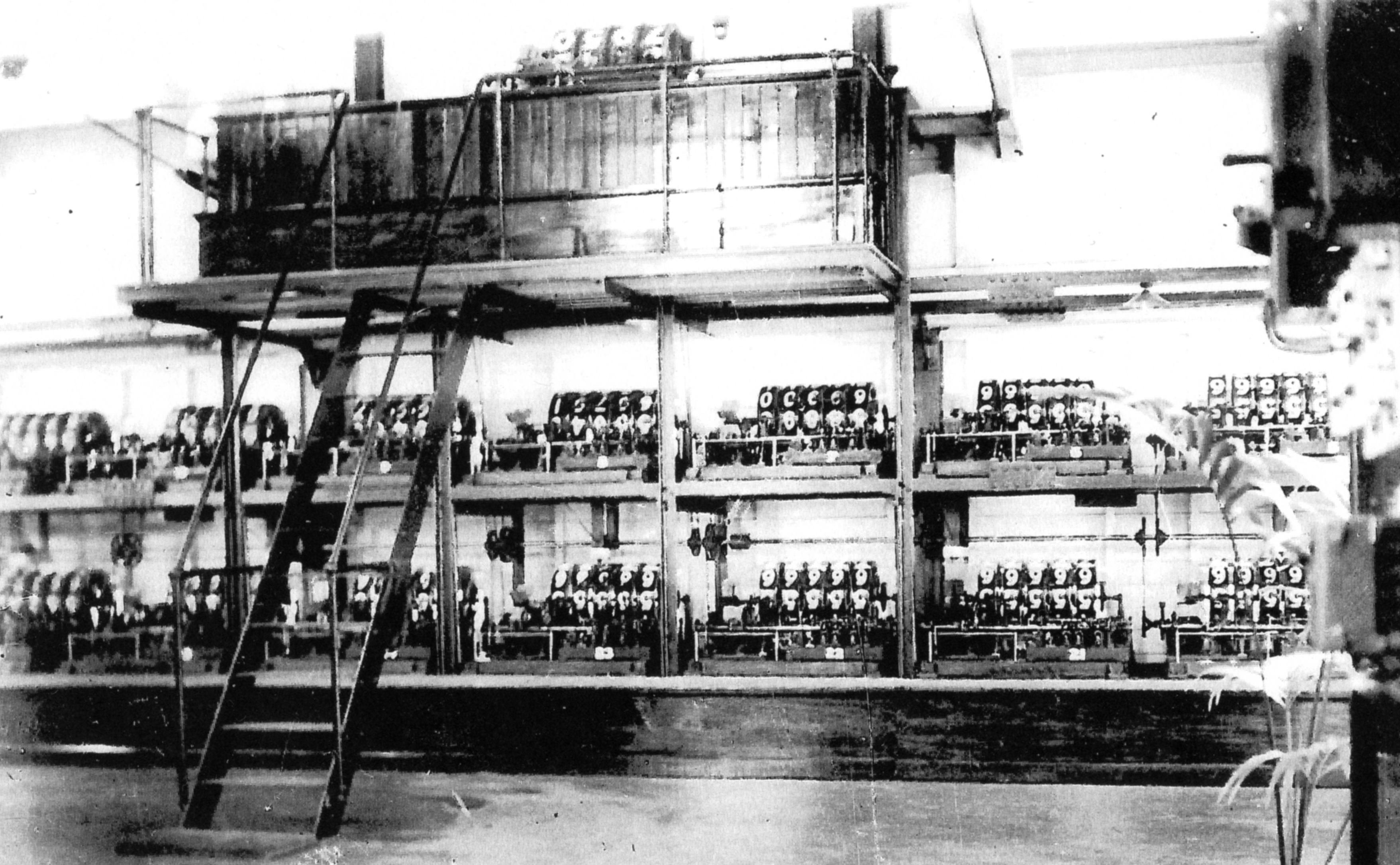
For the extreme sites, like Longchamp for horses, or White City for dogs, special adders were constructed. These were very large and seem to have had individual motors though none has survived for us to inspect. The amount of machinery in these sites was astounding, occupying a great deal of space - at Longchamp there were many of the adder units like the one below (perhaps 84 of them). More details on the Longchamp totalisator are here.
35-Escapement Adder, Longchamp, 1927
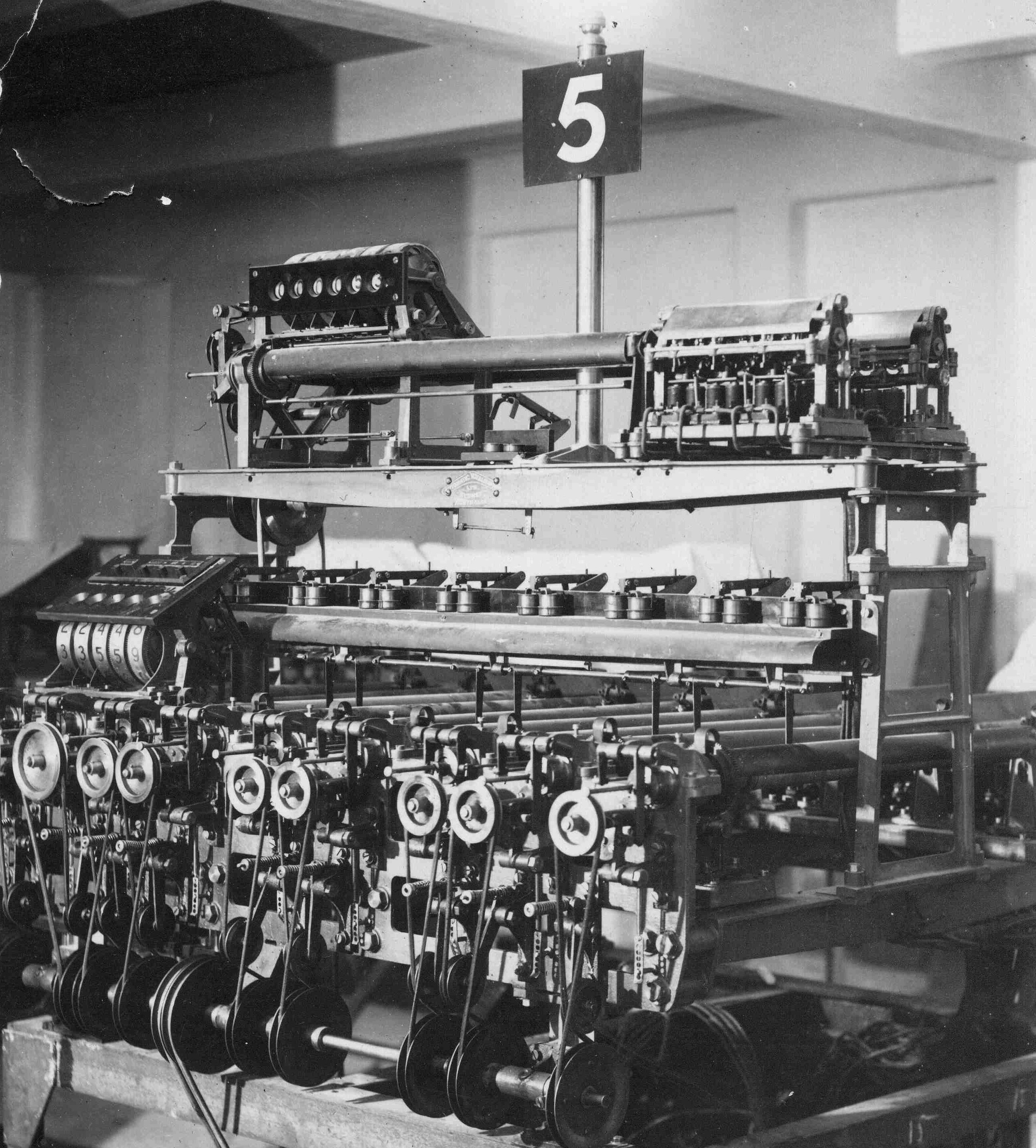
For less demanding sites the approach taken was to house all of the adders in one unit. All of the adders were driven by one large electric motor via a common drive shaft. The whole collection of adders was housed in one frame to give an arrangement that was quite sparing of space compared to the past. The following is believed to be the second machine at Ellerlsie, 1922.
Second ATL Totalisator at Ellerslie (From Auckland War Memorial Museum.)
The relationship between adders and counters also changed over the years. Some early machines had an adder/counter designed as a unit. In others the adders were located separately and their rotation communicated to counters as a series of pulses. With this arrangement it was possible to have remote displays of the betting totals.
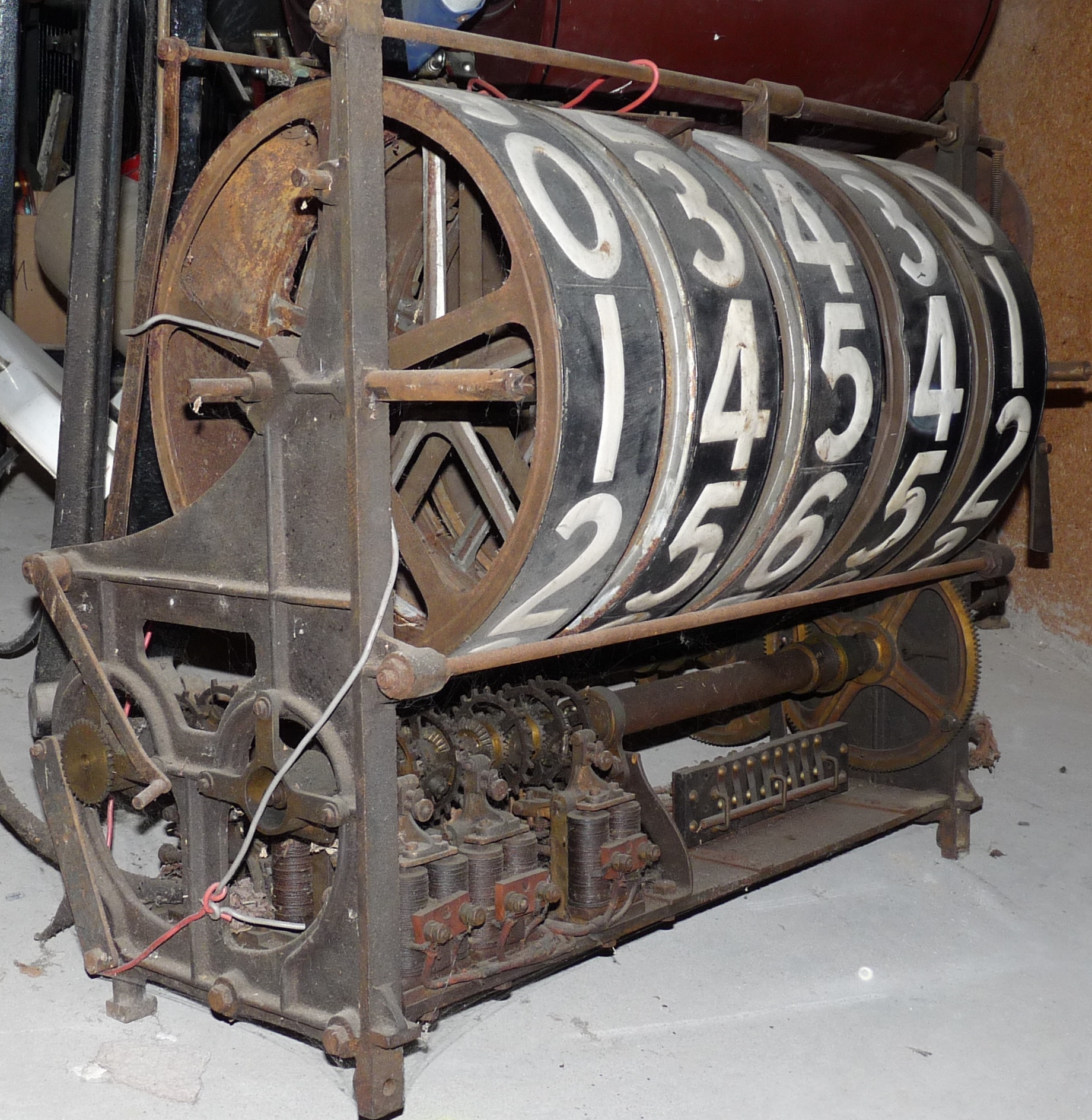
Combined Adder/Counter Assembly
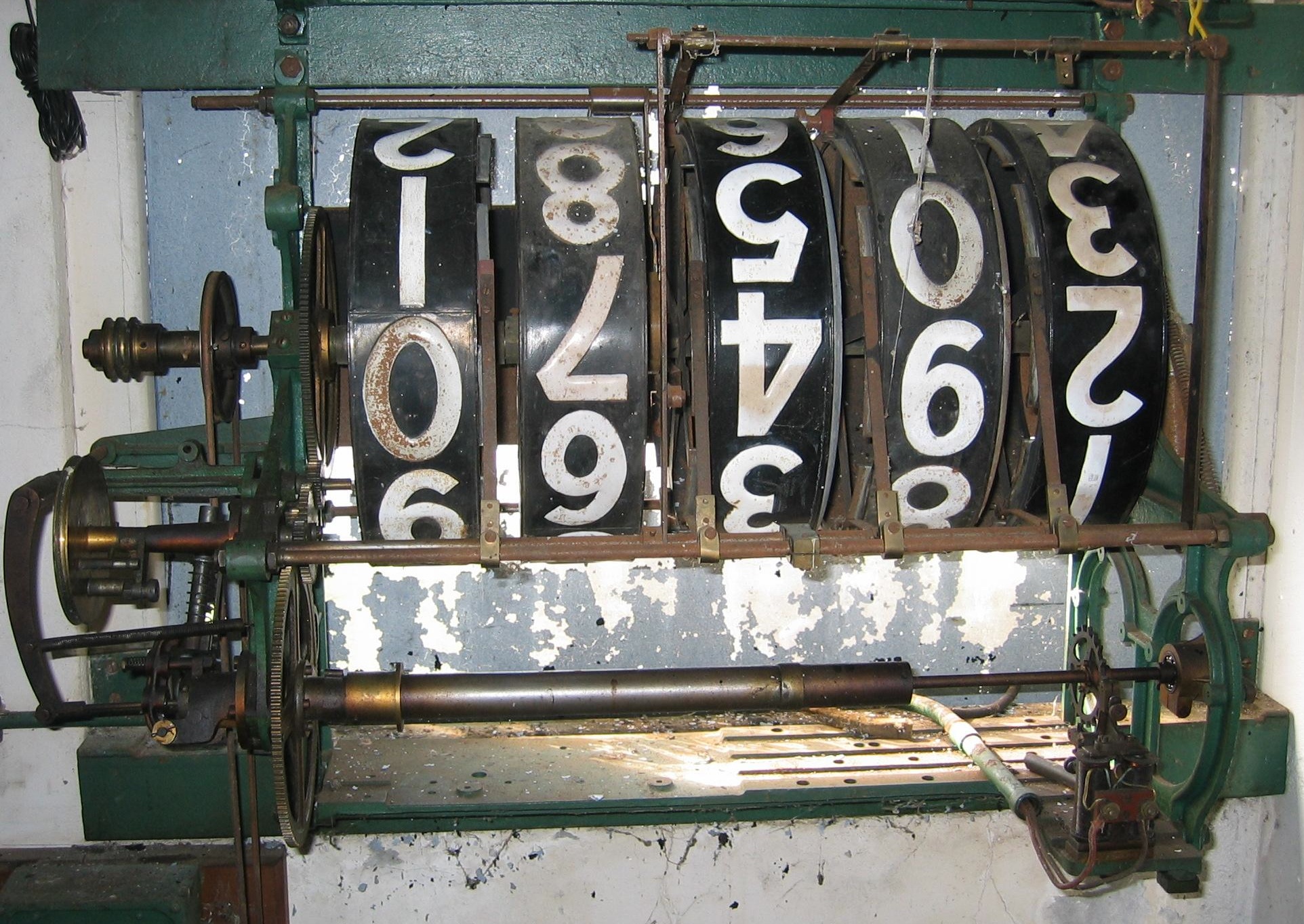
Grand Total Display, Awapuni
In the images here, that on the left is a adder/counter combination in the Ferrymead Museum storage - likely from the first machine at Riccarton. The picture on the right is a grand total display counter at Awapuni, remote from the adder. It is incremented at the "tens" position by the escapement at the far right.
A great deal of effort went in to perfecting counters and dealing with their inertia in starting and stopping. An ingenious buffer device was developed for storing rotation of the counters if the increments arrived more quickly than the counter could be safely accelerated. (In the rightmost image above the buffer is the tubular device in the left foreground.)
However, in the end this development turned out be of short duration as the totalisators moved to displaying expected dividends rather than exact numbers. It was realised that the dividends (and, indeed, the numbers) did not have to be displayed accurately to the public - a close approximation was near enough to guide the bettors. However, accurate totals still had to be recorded and this was performed with small fast low-mass counters (made by the American company Veeder-Root) attached to each adder. (Indeed, with multiplexing, these small counters were capable of summing all bets serially at small courses and machines were eventually made for small applications that did not use shaft adders. And there were TIMs made that recorded the sales on all horses so that totals could be maintained by hand without any other further machinery at all.)
The first automatic machines could only assist betting for "win". There are endless other bets possible (as can be seen with the modern tote), but these do not share the advantage of "win" that it is easy to predict likely dividends. However, there were two types of bet, doubles and place, for which compromises were made so that they were introduced fairly early on.
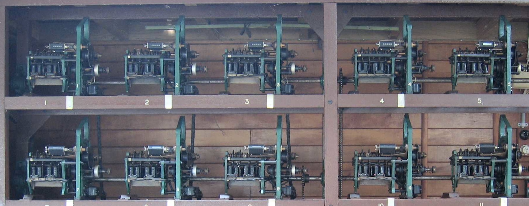
Portion of 6x4 Doubles Totalisator Machine at Awapuni
A doubles bettor simply has to predict the winners in two separate races. Because this is a much harder prediction than for a single race the doubles winner will typically result in the excitement of high dividends which is why the bet was introduced. It has also been claimed that by making one of the races in the double early in the programme the bettors were encouraged to arrive early (and so bet more.) There is nothing complex about a double bet in concept - the trouble is that because there are two races involved the range of possible combinations is squared - for example if races normally have up to 16 horses then doubles betting must allow for 256 possibilities. Being able to predict the expected return would require far too many adders, and even keeping track of totals would be a challenge (though the Power House Museum does have in its store a mobile tote with 256 counters that was operated in Sydney.)
Doubles betting pre-dates mechanisation. In New Zealand doubles were allowed, then banned, then allowed again under restrictive rules. There is a surviving manual tote building dedicated to doubles at Riverton. The compromise made to facilitate doubles betting, both manual and mechanised, was an exchange system - bettors bought doubles tickets specifying a winner for the first "leg" and, if they won, they could exchange their winning tickets (with no extra payment) to wager on a winner for the second leg.
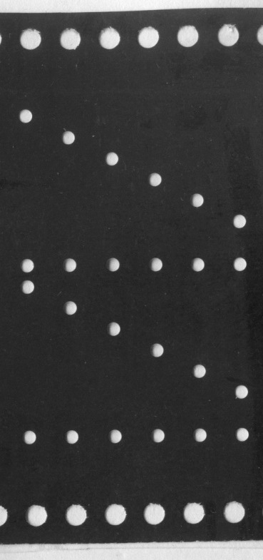
This was simple and effective. Mechanical doubles totes would just sum the bets on each horse. There was no display involved so the machines were very straightforward, for example, the section of doubles machine at Awapuni shown above (actually a 6 by 4 array of adders). In the 1950s a different approach was taken; with the realisation that doubles bets did not have to be counted for all horses, in order to calculate a dividend it was adequate to know how many bets were made in total and how many predicted the winners correctly. ATL developed a "true" doubles system whereby bets were made on the two winners at once and were recorded on very wide (16-track) tape as they were being made. After the final race the tape was run and the two winners known the tape was scanned to find the totals needed. (Piece of tape courtesy of Mr Del Linkhorn.)
A place bet is a wager that the horse backed comes in first, second or third. (Usually changed to first or second for a small field; in many parts of the world place means first or second and our place is called show.) When there was only one pool and one machine, rather than "winner take all" this was sometimes treated as being a place bet with the pool being split 60% for the winner and 20% each for second and third. This was not an attractive proposition to those who would prefer the larger dividend of a win - it was better to have two different types of bets, both win and place.
For place betting the problem is not that there are many possible different bets but that the dividend paid for any horse should depend on what three horses are placed (on the assumption that the wager should be returned and the remaining pool split three ways.) This is actually an intractable problem. In most countries where true place bets are placed the solution is just to not predict dividends, leaving the punters to use the win dividend prediction as a rough guide. However, the approach taken to place betting in Australasia was to redefine the place dividend - it is calculated by simply splitting the total pool of place bets into equal thirds for each placed horse. Although simple, this is actually unfair to those who back favourite horses for a place, but it is just something that we have got used to.
With this approach the place dividend may be predicted by the same means as for win except that the grand total of place bets needs to be divided by 3, manually, or, in the case of a machine, by mechanical gearing. So, antipodean place betting isn't a big deal for totalisator technology, but it is expensive as it requires that the entire win totalisator be duplicated. There were some installations of special place machines, the first in Perth, Western Australia, in 1922 - initially there were separate machines with dedicated TIMs but later TIMs could sell both win and place tickets. However, introduction of place betting was often taken at the same time as the change of display to show dividends. As we will see, the design of win and place machines were integrated with much sharing of equipment and cost saving so that win/place machines became the standard. (Manual totes for both win and place were also operated.)
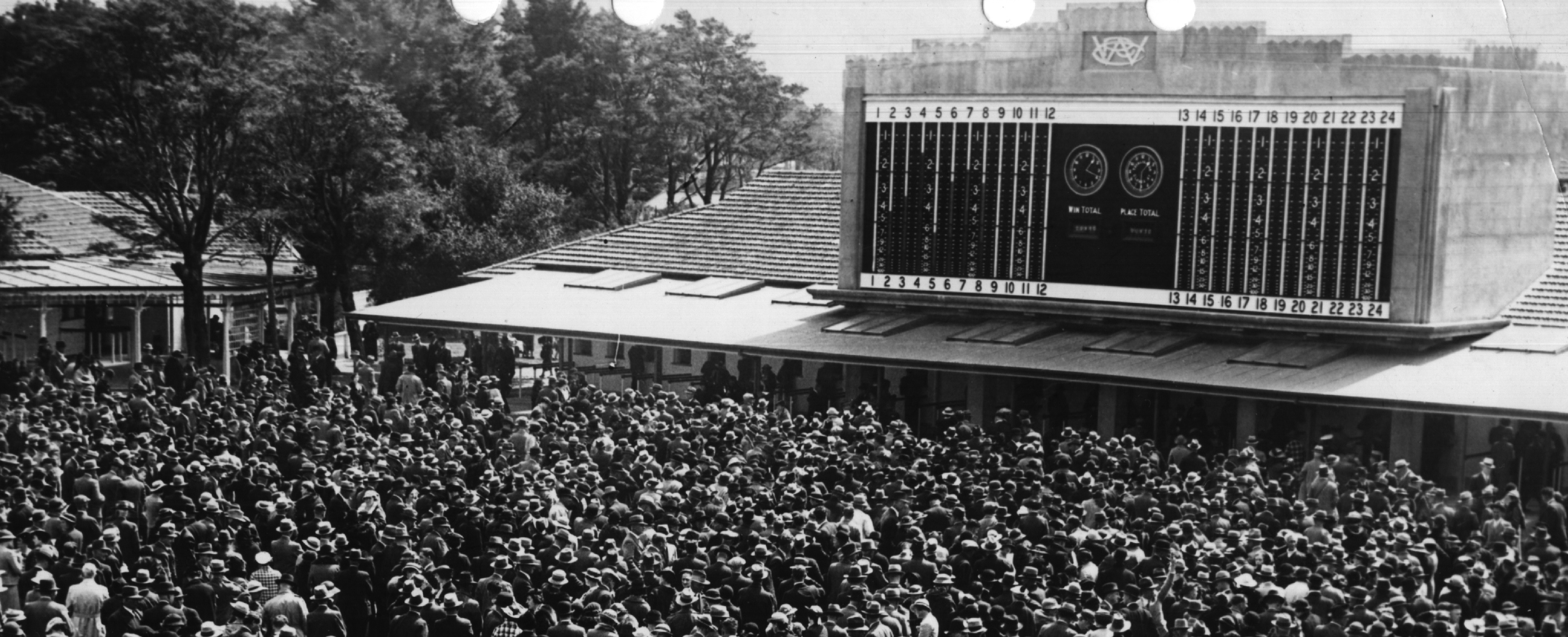
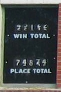
Dividend Display at Trentham (from National Library of New Zealand)
There were a number of methods tried for both displaying and calculating expected dividends - the first ATL site to do so, Harringay Dog Track in London, used "clock-dial" indicators, Eventually, 20 years after the business started, a "standard" form and appearance of a large totalisator was developed and is what is most remembered, typified by the final Trentham totalisator building above. Many of these machines operated for 30 or more years until replaced by computers. The expected dividends were shown as barometers which were actually coloured strips of material, such as canvas, that were lowered against a different coloured background. To display both win and place dividends two strips of different colours were used as the white and orange seen in the Awapuni totalisator display below. (The were other forms of barometer used with manual totes - place on top of win, or pointers.)

Dividend Display - Awapuni
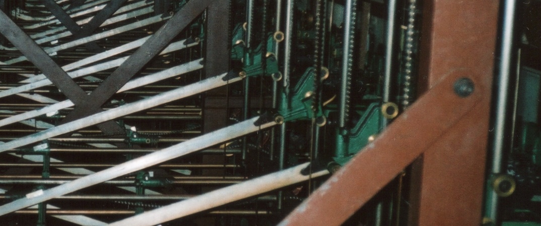
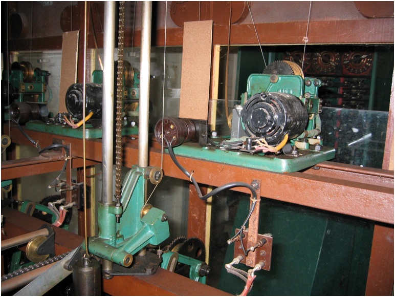
Vertical Sliders
This class of machine was really two machines in one - one side a row of win adders and the other side a row of place adders, though they did share a common frame and motors. The device for calculating the dividend was very clever. There were a set of vertical sliders, one for each adder, that were moved to represent the value recorded by the grand total adder - all the win vertical sliders were at the same common elevation (as were all of the place sliders at their common elevation). In this image you can see the win sliders, the green thingies, all lined up. These vertical sliders start at a low position and are gradually raised by the rotation of the win grand total adder.
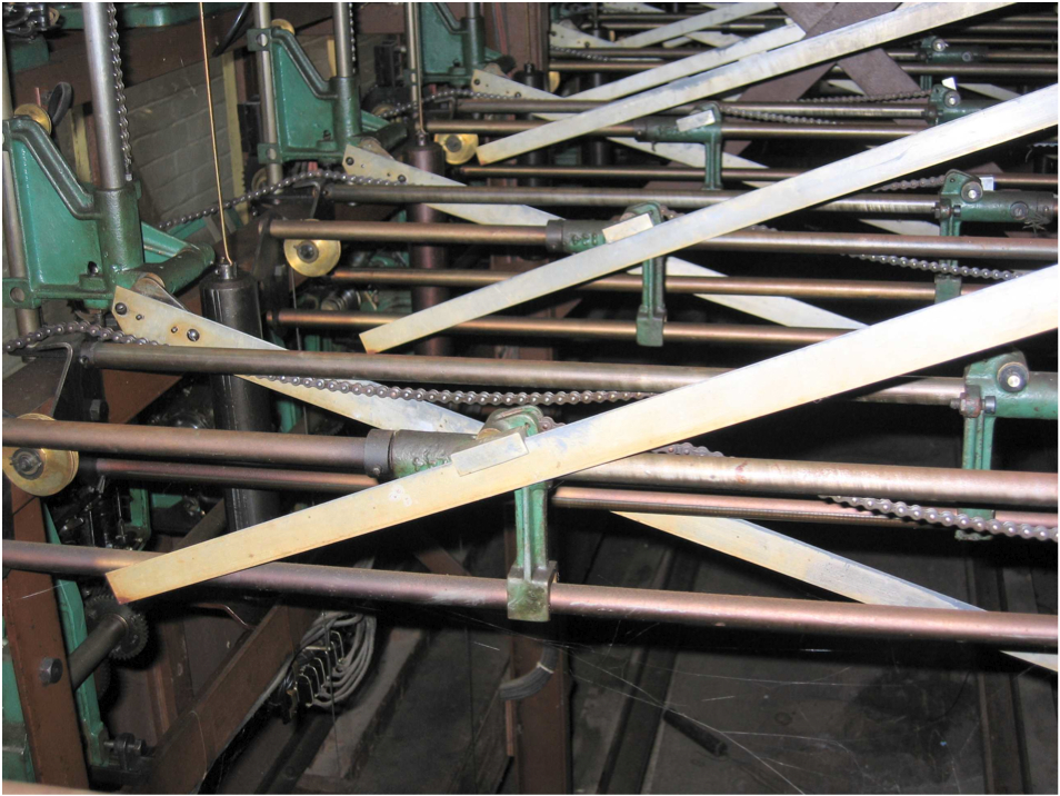
Horizontal Sliders
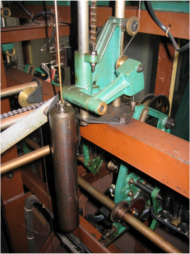
String being Pulled
Each horse adder had its own horizontal slider that was moved to represent the value recorded by that adder. It was initially close to the adder side and was dragged across by a counter-weight as the value on the horse adder increased and its chain released. To the vertical slider was attached a light-weight metal rod that could swivel at the point of attachment. The other end of the rod was held by the horizontal slider, though free to move. The rod was thus the hypothenuse of a right angled triangle with the vertical side proportional to the grand total and the horizontal side proportional to the the horse total. So, the slope of the rod represented the expected dividend - the steeper the rod the higher the dividend would be. (The horse with the largest number of bets has furthest horizontal extent and the lowest slope so shows the lowest dividend as expected.) What was needed next was a way of measuring the angle - any sensible function of the angle would do the trick.
Internal Dividend Indicator
The trick was that the rod is attached through the pivot to a wheel that is pulled by a string that is made taut by a weight. The tension in the string holds the rod in place on the horizontal slider. You can see that a change in the vertical slider's position does not affect the string as long as the slope of the rod remains the same. But if the slope becomes steeper the string will be pulled more, if the slope gets less steep the string will be pulled less.
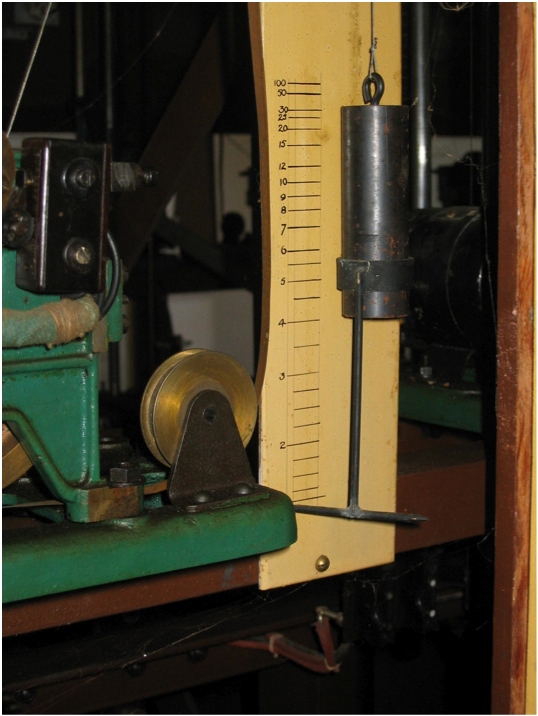
Servo-motor
The weight at end of the string is moved up or down depending on the pull on the string caused by the slope of the rod. The weight has a pointer and a scale that it calibrated so that the higher the weight the higher the divided shown. The string runs via a pulley attached to a servomotor that lets-out or reels-in a cable attached to the strip on the outside indicator so that it shows the same expected dividend to the crowd outside.
Being a physical device the dividend prediction hardware could only handle bet totals up to a fixed maximum. Usually, it was possible to select from a small range of maximum totals by changing gearing on the outputs of the adders. The overall totalisator - the number of ticket stations, the time taken to issue a ticket, and the time between races - was balanced such that the maximums were not likely be exceeded, but, if they were, it was possible to operate the displays by hand, bypassing the mechanical prediction.
These win/place, barometer, totalisators were large and complex machines. They were quite tricky to maintain and operate - reset procedures had to be performed carefully between each race. But they were very reliable in showing approximate dividends while recording accurate totals on the small counters attached to each adder - these values were read out manually and used by the tote operators to calculate actual dividends. The machines were of elegant design - the post-war machines were enclosed in "stream-lined" cabinets. The totalisator engineers maintained their machines carefully and took great pride in their smooth operation and appearance.
As has probably become clear, at the time of writing, there were only three large machines surviving in New Zealand, Riccarton, Trentham, and the condemned machine at Awapuni. Riccarton and Trentham are machines of the early-mid 1930s and Awapuni about 10 years younger. Here are links to further information, mainly images, about these surviving machines.

