
Computer Science
Totalisators: First Automatic Totalisator
The world's first automatic totalisator machine was set operating in 1913 at the Auckland Racing Club's grounds in the Ellerslie suburb of Auckland. The machine was designed by Sir George Julius, the founder of the Australian company "Automatic Totalisators Limited." There is no known detailed description of the machine and no portion of the machine has been preserved. Here we attempt to describe the machine as best that we can - what it did, how it worked.
This description is based on the information that is still available. We have a set of photographs taken as the machine was being assembled and tested in Sydney before being shipped to Auckland. There are also some photos of the machine taken when it was installed and operating. There are patent documents filed by Julius, particularly one lodged in 1915. This patent doesn't describe the Ellerslie machine specifically, but some parts definitely apply - also there are some improvements mentioned in the patent that can be read as implying some negative aspects of the 1913 machine.
We can be very clear about many aspects of the machine from study of these photos and patents. However, because there is no detailed description it sometimes takes a lot of reasoning to decide what the machine was like. This detail might perhaps be of interest to one or two enthusiasts but not to the majority of readers. Hence, this description is written on two levels. This top-level overview should be understandable by any reader but it links to more-detailed descriptions of some parts of the machine that might be harder going.
The Ellerslie machine was a mechanisation of the process of "pari-mutuel" betting invented by Joseph Oller. Oller conceived the concept of pool betting that may be applied where there is a single winner from a field of competitors. Totals are kept of the amount bet on each competitor together with the grand total of money bet on all competitors. When the winner is known, those with bets on the winner are awarded a share of the grand total (after deduction of a commision) proportional to the size of their bet. Oller enhanced the excitement and interest of horse-race gambling by displaying the totals on each horse and the grand total in "real time" as the bets were lodged - potential punters could see what other gamblers were backing and could estimate returns if they won.
Until the arrival of the 1913 Ellerslie machine, pari-mutuel gambling, which had become known as the totalisator, was run manually. As bets were made the totals were counted and displayed - at the start on chalk boards but later with large impressive numerical displays. Manual operation could work well if organised properly and continued at small race courses into the 1960s. However, the totalisator was highly subject to fraud and had to be rigorously controlled. One criterion imposed by authorities was that the totalisator must be closed with complete and final totals before any race was run. At bigger race courses, where there were tens of thousands of gamblers, this could result in unacceptable delays. It was a problem crying out for mechanical solution. Happily, when the race course clubs were given, by legislation, the monopoly on gambling they had the funds to pay for novel solutions. This happened relatively early in New Zealand which explains why the Auckland Racing Club was able to pay for the first automatic totalisator in 1913.
Top
The new machine was housed in its own building - this was an existing structure built for operating the prior manual totalisator and adapted for the new purpose. In this photo of the "tote house" you can see displayed in the middle section of the building the number of 10-shilling bets on each horse (from horse number 1 to horse number 30) with the grand total of all bets shown in a larger display dead-centre. Notice that there are three rows of horse totals, 10 per row.
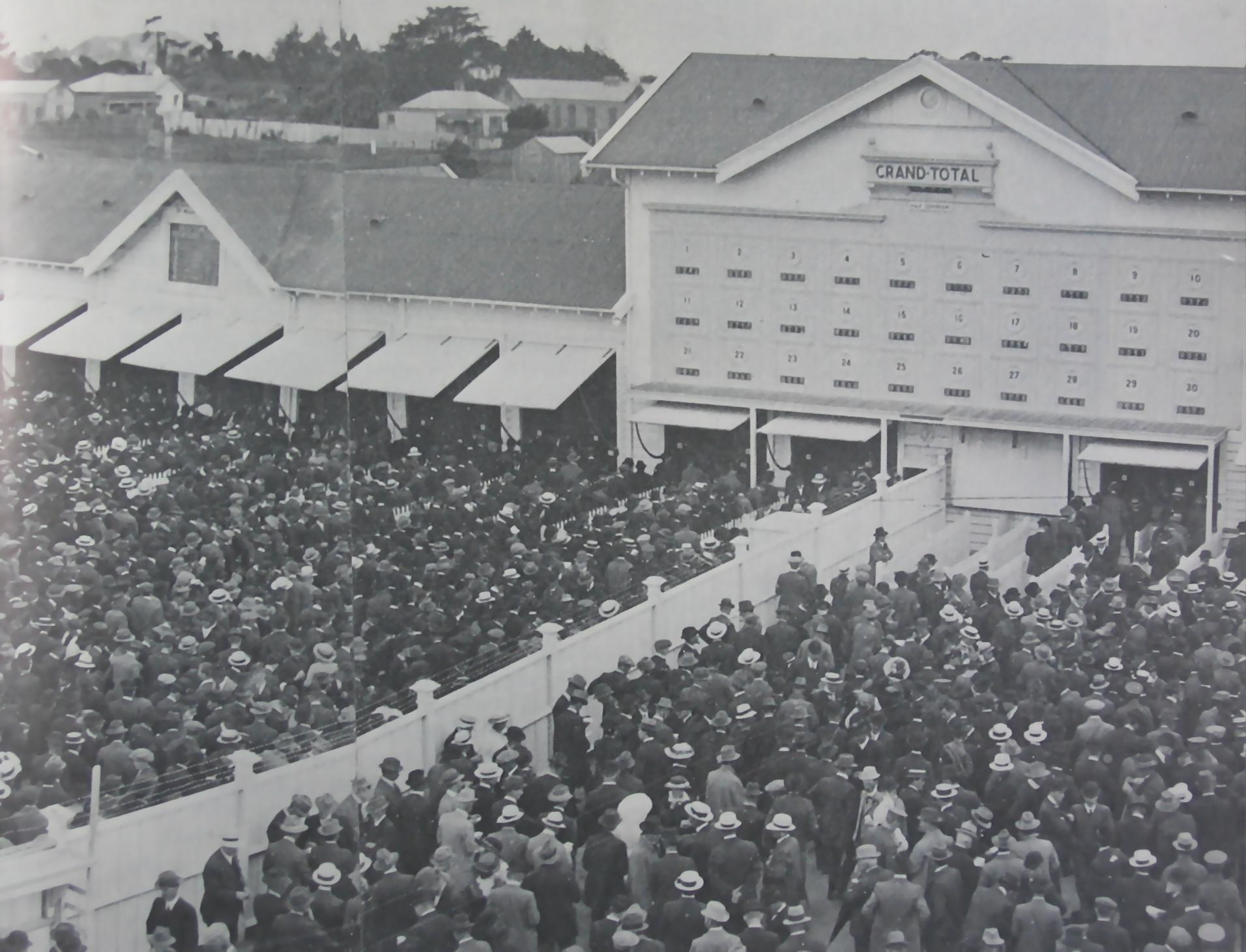
(from "The Noble Breed")
The gamblers are queued up in front of the ticket selling stations which are under the shutters. There are 7 shutters in the wing to the left, 6 in the wing to the right and 4 in the middle, so at two stations per shutter there is room for 34 ticket stations, but only 30 were provided. The fence (topped with barbed wire!) runnning to the middle of the tote house was used to separate the members of the racing club from the general public.
Nowadays, we are used to data being displayed remotely. However, that was not yet possible in 1913. The totals displayed are actually, as we will see, represented on "wheels" in the machine itself. You are looking through small windows at the totals displayed on the machine - the machine occupies the entire space behind the central part of the tote house.
The exterior photo shows the way the machine worked from the punter's point-of-view. There were two values of tickets sold at different stations but all could handle bets on any horse. Most sold tickets of 10 shillings value and some sold tickets of 20 shillings (one pound.) (Even the minimum bet was a lot of money in those days but if you wanted to bet more you could buy multiple tickets, though there was, apparently, one station that sold tickets of 5 pounds value.) You queued at a ticket selling station that corresponded to your intended bet value. For every 10 shillings you wagered on a particular horse number you should see the total displayed for that horse number increased by 1 and the grand total also increased by 1. From the punter's view it seems a fairly simple process, but, as we will see, it was very difficult to make a machine do this work with the technology of the time. The central problem to be solved was how to register the correct total when all 30 ticket stations sold tickets for the same horse at exactly the same time, but there were also many other practical problems that needed resolution.
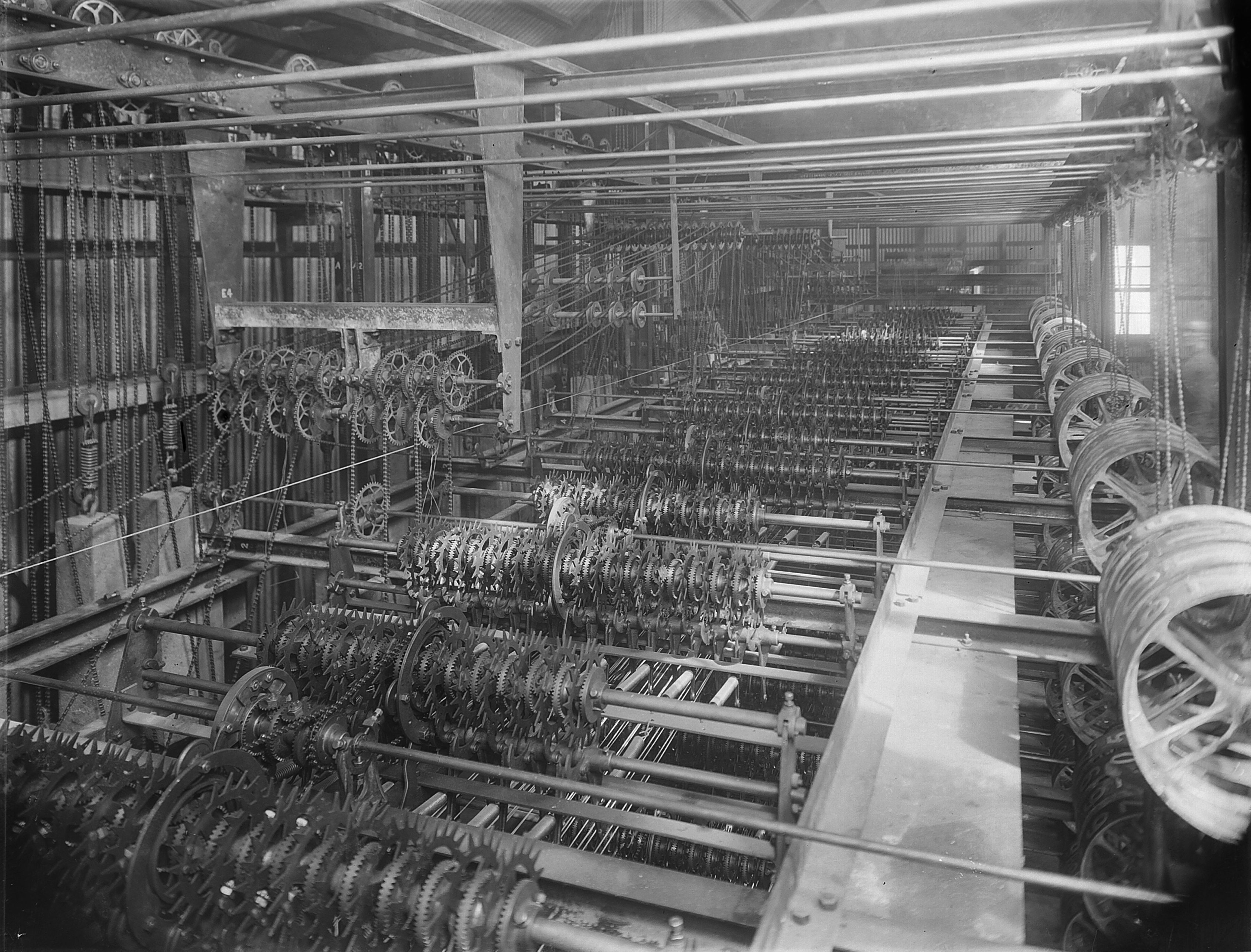
The machine comprised a number of different types of specialised device each replicated many times. We have seen the counters through the windows - their purpose is to count the number of bets on each horse individually, and on all horses (the "grand total"), and also to display the totals so that they are visible to the punters gathered below the machine. You can better see the size of the machine and its counters in this image of the machine being assembled in Sydney:
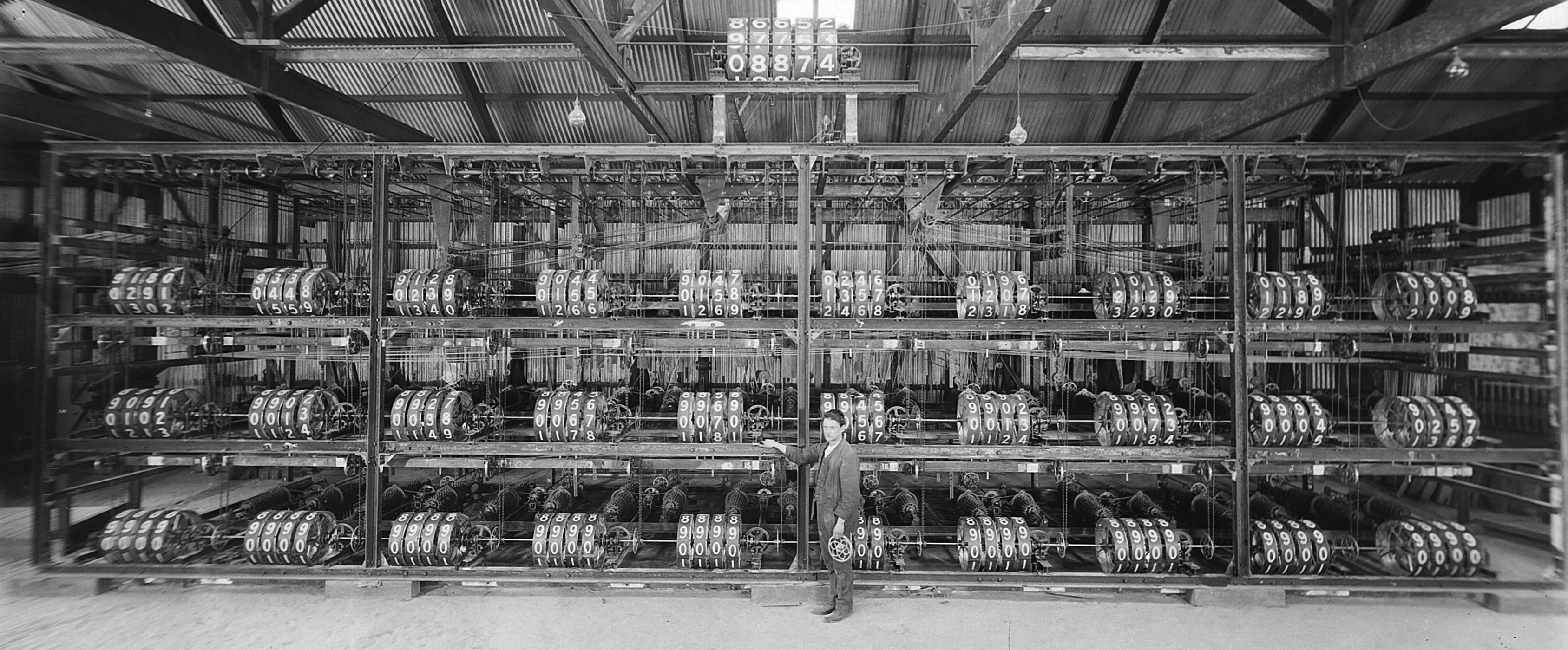
Machine assembled for testing at Sydney (from Power House Museum)
The counters are in three layers of 10 with the larger grand total counter on top. The counters display totals as conventional decimal numbers. However, internally totals are represented by the amount of rotation, from the commencement of betting, of shafts. Each rotation of a shaft represents 20 unit bets, so at any time a particular shaft represents a total given by 20 times it's number of full rotations, plus whatever fraction of the current rotation. Every display counter has a rotating input shaft as may be seen in this diagram from the 1915 patent application:
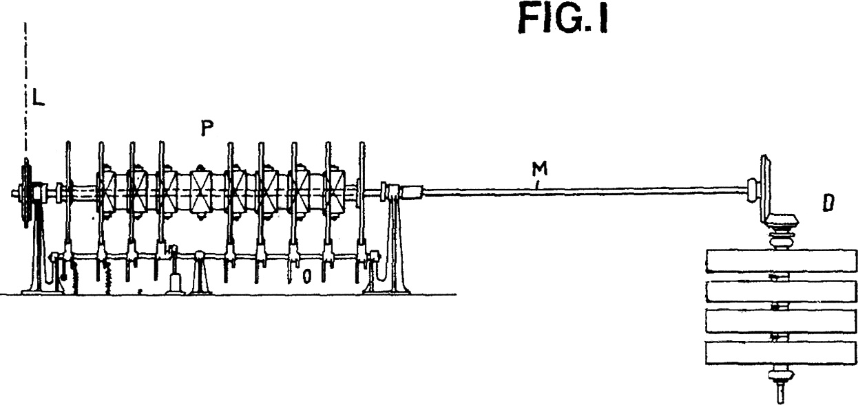
The counter (D) is designed so that it increments its displayed total by 1 for every 1/20 of a rotation of the shaft (M). When a unit ticket is sold for a particular horse number, the machine ensures that the input shaft to the counter for that horse number is rotated by precisely 18 degrees. The basic way that this is achieved is that the display counter input shafts are continuously placed under "pressure" to rotate but only allowed to rotate when a bet is issued. This is assured by the use of an escapement mechanism adapted from the design of clocks.
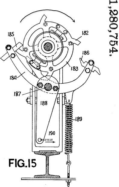
To explain how this works we can modify a diagram from the 1915 patent application. At the top is a wheel with four teeth that is pinned to a central shaft represented by the black circle (the shaft is perpendicular to the diagram.) The shaft and wheel are being impelled to rotate in the direction shown. However, the wheel is stopped rotating by the pawl (185) connected to the rocker arm (184). The rocker arm can turn around a pivot (187) and can be made to move by tugging the "string" (190) attached to the middle arm of the rocker(188).
The machine ensures that a bet on a horse causes a tug on the string (190) which moves the rocker. This removes the pawl (185) from the tooth of the wheel and allows the wheel and shaft to rotate. However, the movement of the rocker puts the other pawl (186) in the path of the tooth (182) and allows only a limited rotation. When the string is released the spring (189) causes the rocker to return to its original position, removing the second pawl (186) allowing further rotation which is checked by the first pawl (185).
In this example, the issuing of a ticket on a horse allows the shaft to rotate precisely 90 degrees. In our machine the principle is the same but, as seen here, the escapement wheels have 20 teeth so a unit bet allows a rotation of 18 degrees.
Let's summarise the main components that we need to describe in more detail:
- There has to be some power supply mechanism impelling the shafts to rotate.
- There has to be an input mechanism that makes the sale of a ticket move the rocker arm on the appropriate escapement.
- We have shown how one ticket sale can allow a counter input shaft to rotate but the problem is that there are many (30) ticket selling stations that could potentially issue tickets for the same horse at the same time. So, there needs to be a device that ensures that all of the ticket sales are registered - we will use the later ATL name of shaft adder for this device, though in 1915 Julius called it a "computer". (The adders for horse totals incorporate the escapements mentioned above.)
- Finally, there needs to be a device to count the total number of bets on all horses - we will call this the grand total adder. In later machines the grand total adder and the horse adders were identical devices - in this first Julius totalisator the grand total adder was quite different.
The general plan of the central part of the machine is as follows:
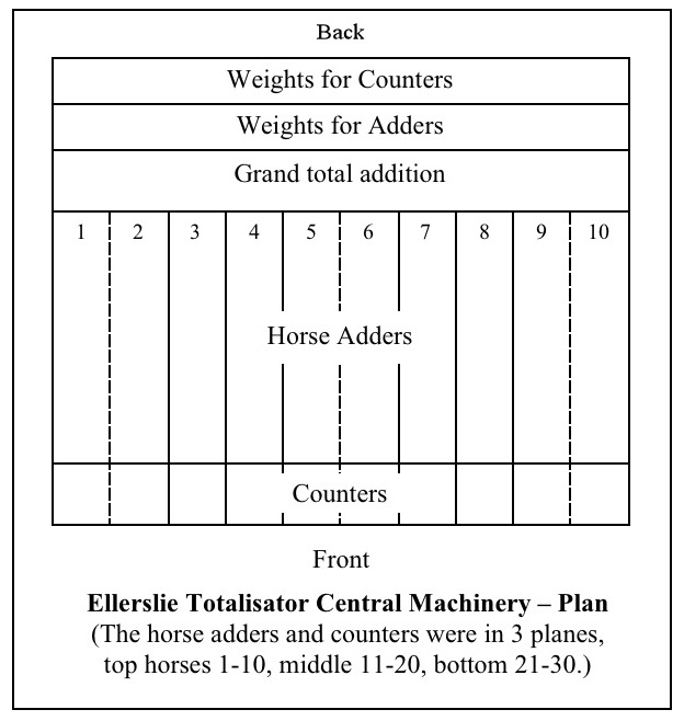
Here is a photo looking across the top plane of the machine. Most of the components are visible in this picture:
Top plane of machine (from Power house Museum)
Top
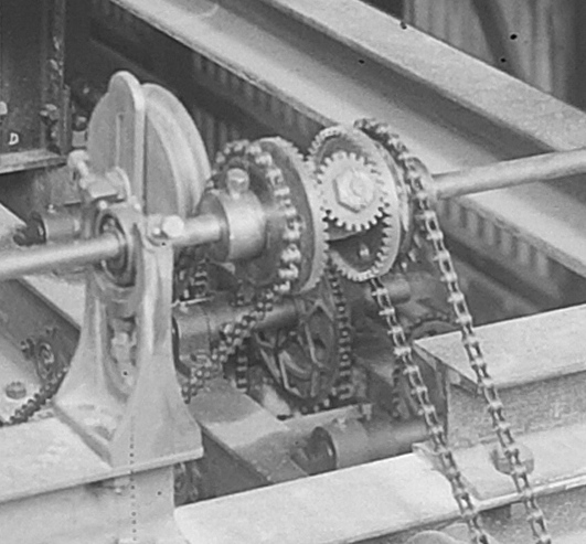
What impels the shafts to turn? In the "Fig. 1" diagram above you can see a sprocket wheel being driven by a chain (L) but that just changes the question to "what powers the chain?" It is its power supply that puts the first Ellerslie machine in the category of late 19th century rather than the 20th century. The machine is entirely driven by clockwork - there is no use of electricity in the machine at all!
At the top back of the machine there are two rows of ratchet wheels.
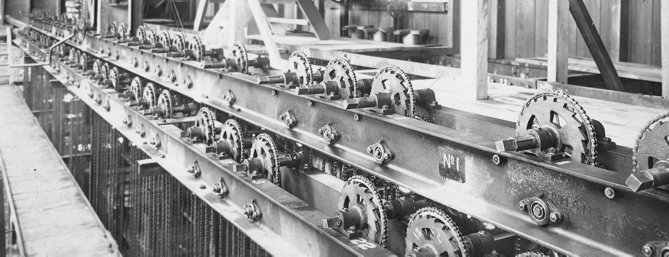
Ratchet Wheels (from Power house Museum)
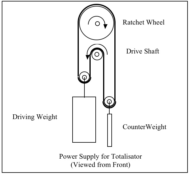
Running over each ratchet wheel is a chain to which is connected, via a heavy driving weight, to another wheel that turns a drive shaft (which in turn has a wheel that connects by a chain to an adder shaft (L)). The chain is kept taught by a smaller counter weight. The driving weight impels the drive shaft to turn, gradually lowering as it does so. As long as the driving weight does not fall too far the drive shaft is provided with a steady driving force.
It was necessary to raise the driving weights between each race. There were about 62 weights needing raising, depending on how many horses were in the previous race. The weights were raised using a hand-crank - you can see the squared end of the ratchet wheel shafts above and a hand crank to the left. There was a platform for the weight-raiser to stand on. The weights could be raised while the machine was in operation without altering the motive force - presumably somebody had to keep an eye on the weights for the favourite horses and raise them before they hit bottom.
The weights were pieces of concrete of substantial mass. It must have been quite an effort to keep them raised. In the image below you can see the array of weights and counter-weights as the machine was assembled in Sydney.
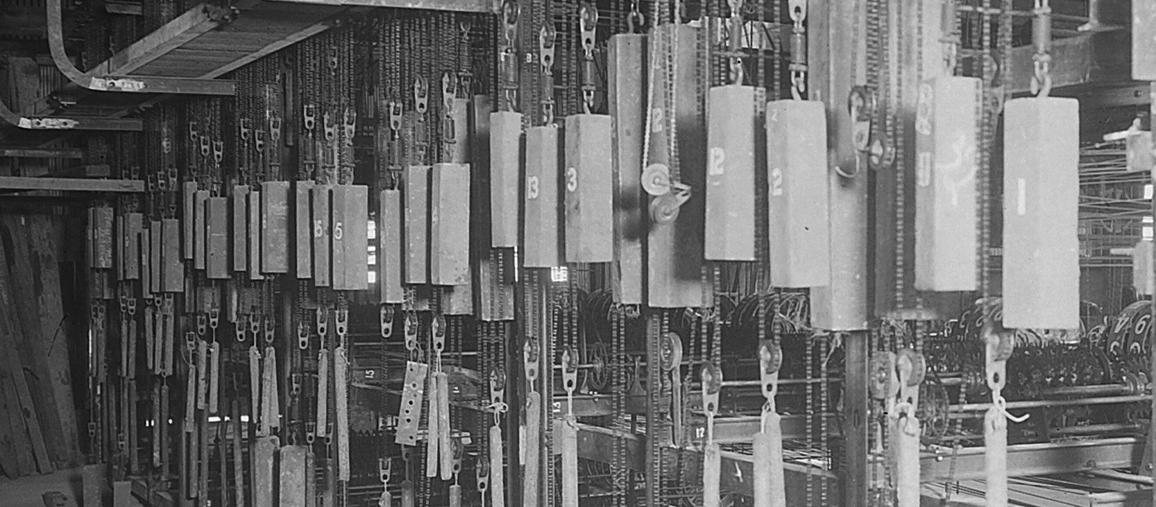
(from Power House Museum)
Top
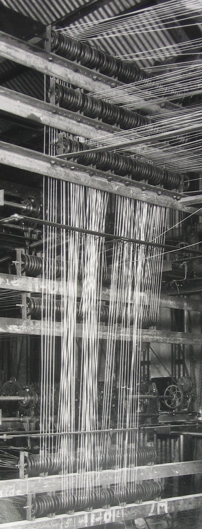
Any ticket issuing station must be able to accept a bet on any horse. As we have seen, in this machine, a bet is registered by pulling the lever on an escapement. As there were no electrical connections there had to be steel wire or cable connecting each escapement to a ticket station. The cable was physically pulled by the ticket issuing station to register the bet.
In the final machine there were 30 cables from each of the 30 ticket selling stations, one cable from each station running to each of 30 "shaft adders" that totaled the bets for a particular horse. So there were 900 cables to be accommodated in the machine! Large numbers of wires carrying electrical signals are relatively easy to handle as they are flexible and can be stowed out of the way because their length and positioning are not very important. However, the cables in this machine had to be strong, inflexible, and kept taut, so the pull on the handle would be transferred reliably up to an adder in the machine. In the image you can see some of the cables running over pullies into the machine being assembled in Sydney.
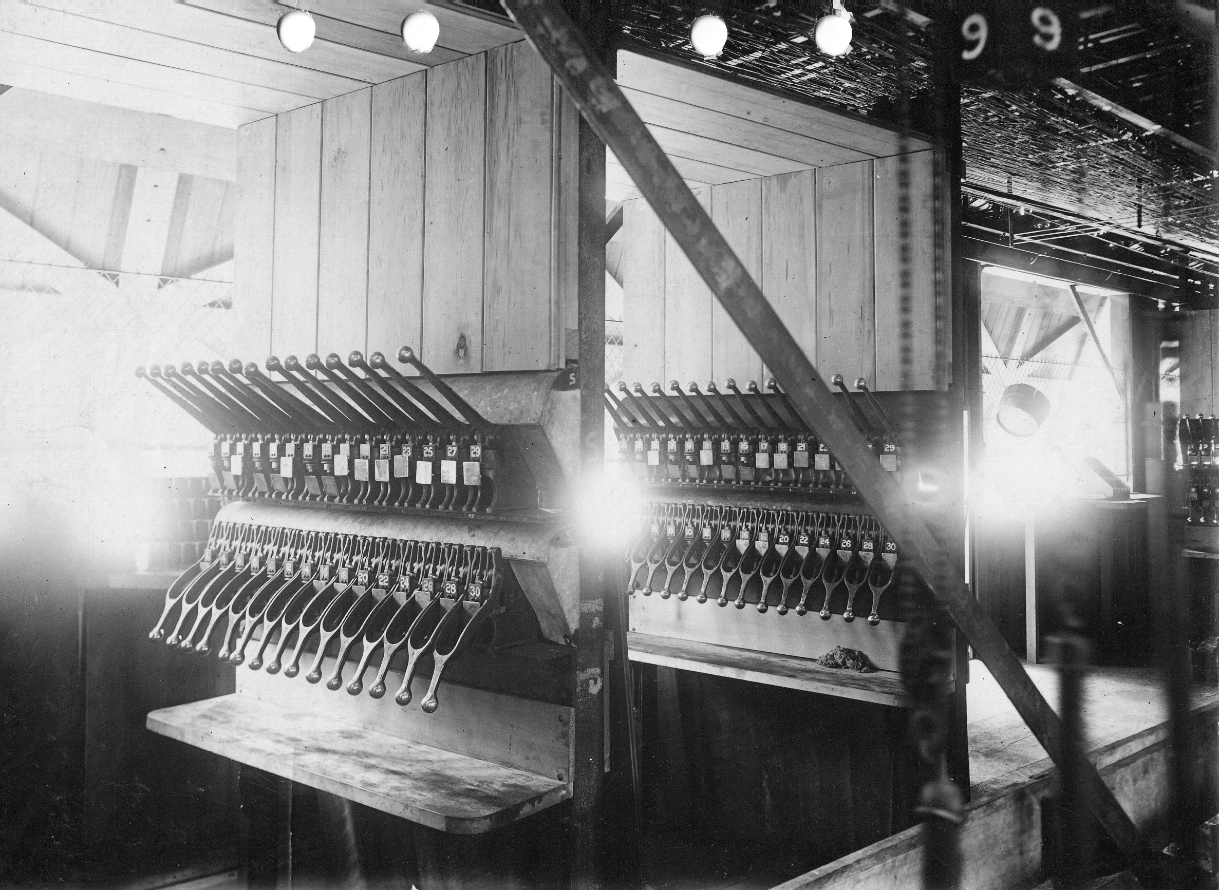
The ideal for ticket issuing is that the ticket is only issued after the bet has been registered in the machine. At Ellerslie, to start with, pre-printed tickets were selected by hand. The operator pulled one of 30 levers, referred to as "beer pump handles," to record the bet and the lever mechanism also perforated the ticket to validate its issue.
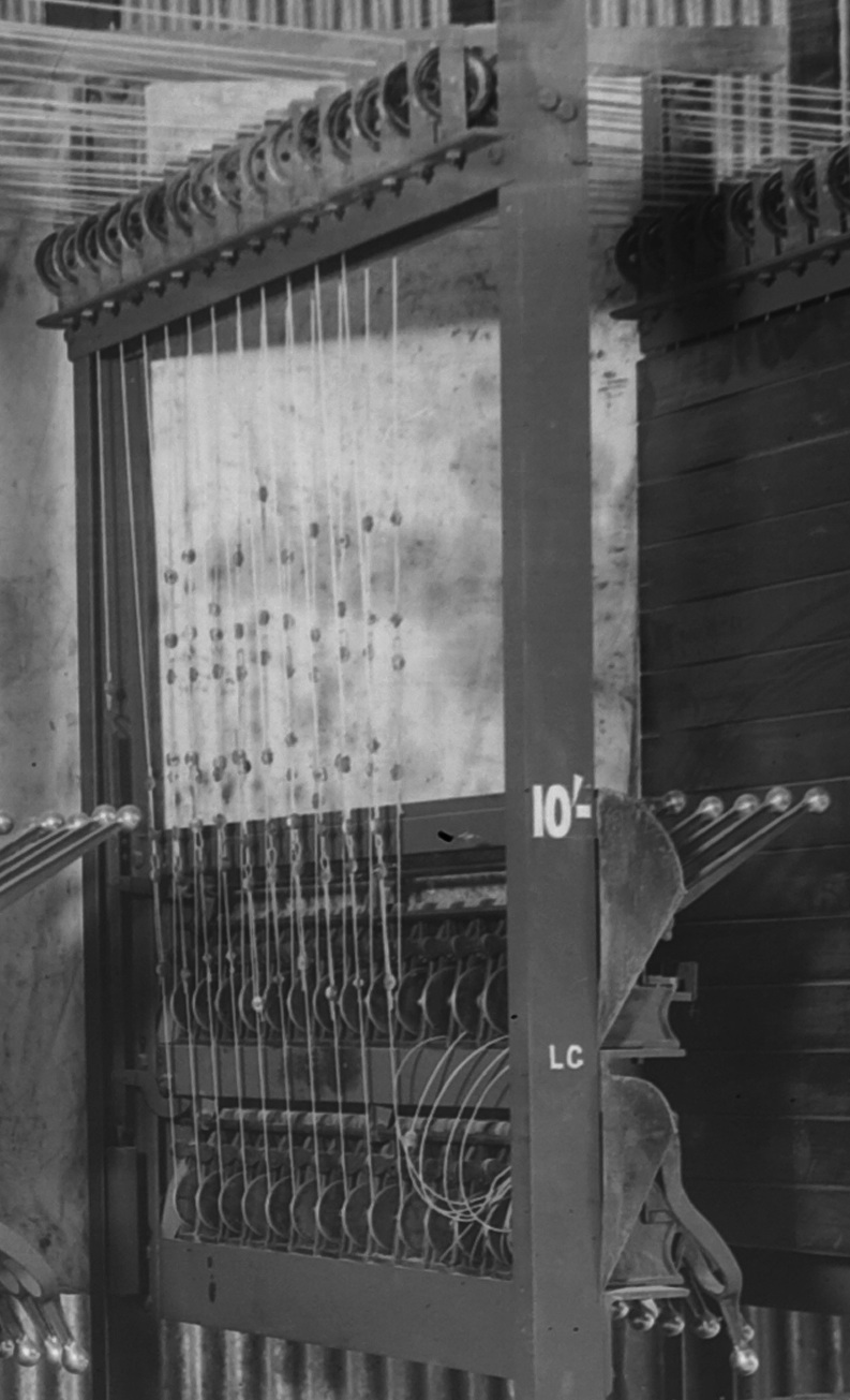
Here is a photo of one of the ticket issuing stations being tested - note the wires running over pullies up into the ceiling space. Each station had two banks of 15 levers, the top for the odd numbered horses and the bottom for the even. To record a bet, the operator would pull down the lever for that horse. This would release an escapement on the shaft adder corresponding to that horse in the central machine.
We have one photo that shows the ticket machines in place at Ellerslie. The wires are hidden in the panelling (but there is a real rats' nest of wires up above.) The ticket window shutters are here seen from the inside.
(from Brian Conlon)
Top
We have seen that the number of bets on any horse is given by the rotation of a shaft that feeds the counter for that horse. The Grand Total counter needs to be fed by a shaft that represents the sum of the rotations of all of the horse shafts. We must now introduce the device that does this job, what was later called a "shaft adder". These are not too hard to understand if you can actually see one working but what we will do for now is just assume that they can be made. Consider the following diagram:
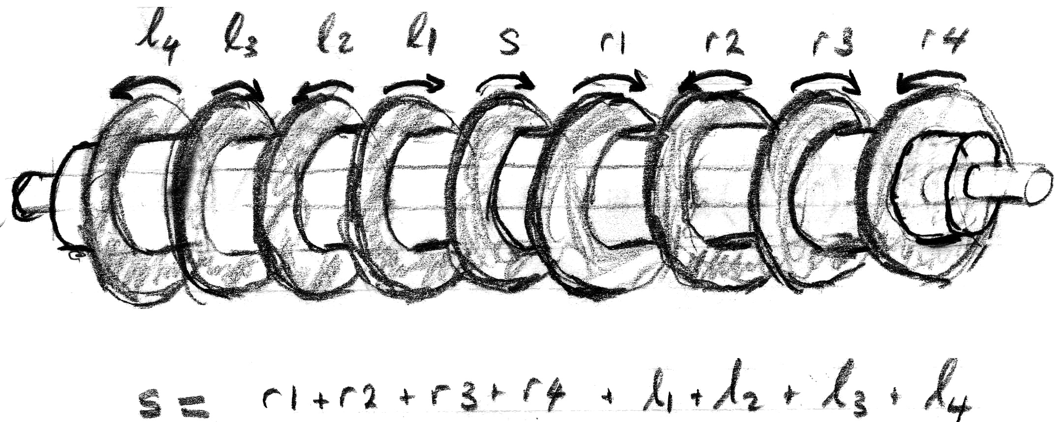
Here we have an archetype shaft adder. Around a central shaft is a cylinder that contains cogs etc. that do the work. Around the cylinder is a series of wheels that are free to rotate. The mechanism ensures that the rotations obey the equation shown i.e. the rotation of the central wheel must always be the sum of the rotations of the other wheels as shown - though some wheels must rotate in the opposite direction to others. These shaft adders can have any number of wheels with the sum equation following the same pattern as this example. If you would like to see how these shaft adders work there is more detail here.
To form the grand total our machine uses two shaft adders to add separately the rotations for the 15 horses totalled in each half of the machine. The one for the left side is:
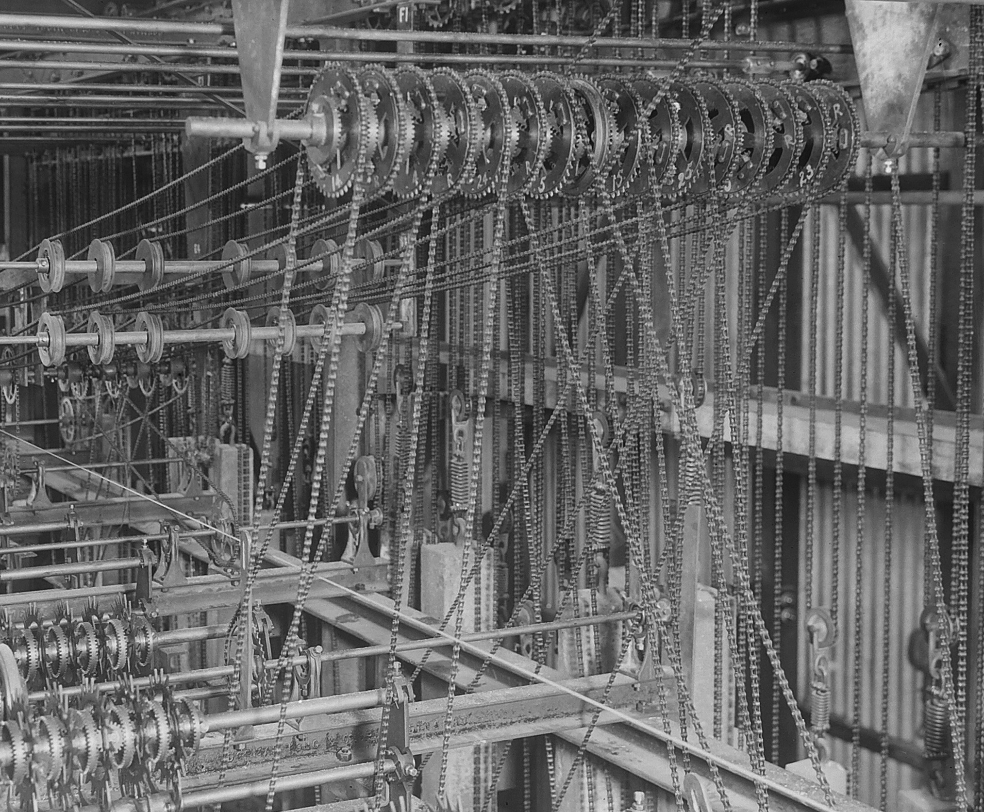
(from Power House Museum)
The line of wheels at the top is an implementation of a shaft adder - in this case the wheels have sprockets to which are connected chains to transfer rotation inputs. In the centre of the adder is the wheel that represents the sum - its rotation is transfered by chain up to the right to the top of the machine. The other wheels are rotated by their chains to reflect the rotation of each horse shaft. For example, at the bottom you can see the shafts for horses, 1, 2, 3, 4, and the chain connecting the shaft in the foreground for horse 4 to the adder wheel up above that is marked "4". Other chains disappear down to the lower levels of the machine to pick up the rotations for other horses.
With a shaft adder every alternate wheel has to rotate in the opposite direction but with this machine all horse shafts actually rotate in the same direction. You can see chains for some wheels being relayed from the distant left. We have a close-up below of the other end of those chains. Here, the rotation from each of 7 horse shafts is picked up then reversed by gearing before being relayed to the shaft adder.
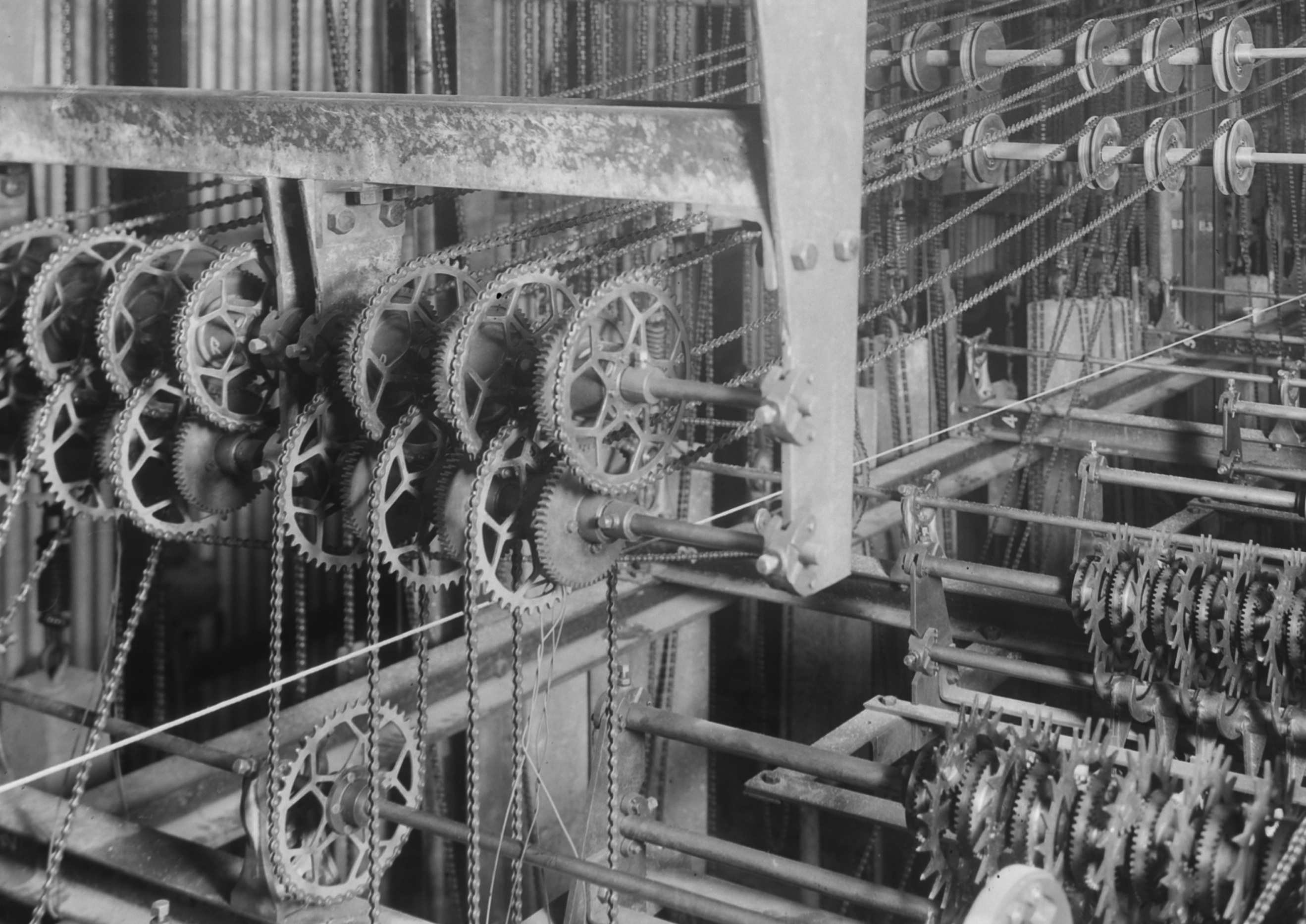
(from Power House Museum)
The right side of the machine has a mirror image set-up which sums the rotations for the other 15 horses. Chains from the right and from the left appear on the top layer of the machine. Here they are added by a minimal variation on a shaft adder. The grand total shaft is made to rotate as the sum of rotations from the left and right. (Actually, 1/2 the sum of the rotations, but this is compensated by the diameters of the input wheels being 1/2 that of the wheels in the shaft adders down below.)
Top
The Grand Total adder sums the rotations representing the bets on each horse. Similarly, each horse total must be formed by summing the bets placed on that horse at each and every ticket selling station. We have seen how the bets from a particular station can be represented by the rotation of wheel that is only allowed to move by an escapement mechanism responding to the sale of a ticket on that horse. For each horse there has to be one escapement wheel for each ticket station. The next trick is to add the rotations for each escapement wheel.
Not surprisingly, shaft adders can be used for this purpose as well. The Grand Total adder works in a positive manner - chains move its input wheels and force its output wheel to turn. For the horse adders the process is kind-of reversed. The output wheel is being driven forward and drives all of the input wheels forward. But nothing can move because all of the input wheels are held in check by escapements. When any escapements are released their input wheels are allowed to move 18 degrees forward and so the output wheel is also caused to move by the sum of all input wheel rotations.
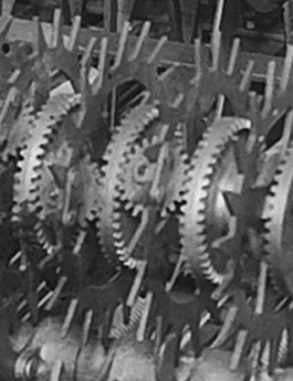
You can see most of the adder for horse number 1 in the image below. As with the Grand Total adder the summing is split into stages. In the foreground is a shaft adder that has 17 escapement wheels, in the background another with 12 wheels, making for 29 ticket stations in total. (There was another 30th ticket station for 5 pound bets - we do not know how these bets were counted.) In the middle is the actual shaft that represents the number of bets placed on this horse. This is being driven forward by the weights at the rear. The shaft, via chains, drives forward both the 12-wheel shaft and the 17-wheel shaft.
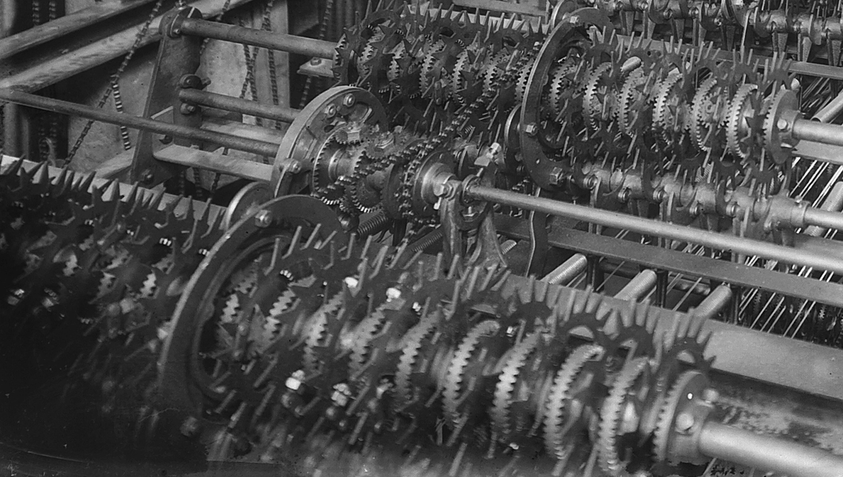
Whenever escapements are released in either of the component shaft adders the output movements are conveyed back to the central shaft by the chains. The central shaft also contains a cut-down shaft adder capable of adding the two rotations. The output of the small adder is pinned to the horse shaft so that the shaft is forced to rotate by the amount representing the new sum.
It seems that the reason for there being two shaft adders is that the 12-wheel shaft represents bets of 20 shillings whereas the 17-wheel shaft is for bets of 10 shillings. The 2-input central adder is designed so that the 20 shilling bets cause double the rotation of 10 shilling bets.
Top
The counters were the parts of the machine that we saw first. Unfortunately they are also the parts about which we know the least. There are no photos of the inner workings of the counters and the 1915 patent application describes in detail improved counters that are unlike those of our machine.
Perhaps it doesn't matter too much at this level of description. The counters comprise a set of wheels on which are written the digits from 0 to 9. From the front, the rightmost wheel shows the units digit of a total, the next left, the 10s digit, then the 100s etc. We do know that each counter has an input shaft and that for every rotation of the shaft by 18 degrees the units wheel should be rotated so the next bigger digit is displayed - a full turn of the input shaft should cause the digits wheel to rotate fully twice.
The real tricky concept is the propagation of carries. When the displayed digit of the units wheel goes from 9 to 0 the 10s wheel should rotate to show the next 10s digit; when the displayed digit of the 10s wheel goes from 9 to 0 the 100s wheel should rotate to show the next 100s digit; etc. If the counter displays e.g. 3999 it should next display 4000. The mechanism for causing this to happen lies within the counter, between digit wheels, which is why we cannot see it.
Matters are made more difficult for our machine by the counters having to display the totals in large readable letters. This makes the counter wheels very large and their relatively large mass causes serious practical problems. It is difficult to start the counters moving (which is why all of the counters have an additional source of power.) Worse, if there is a run of betting on a horse the counter wheels might start to rotate quickly and, when the run stops, it will be difficult to stop the wheels suddenly without causing mechanical stress on the mechanism. It is clear that Julius had addressed these problems even in the 1913 machine but we do not know the details.
Top
We have to bear in mind in our discussion that, although it may seem hard to believe, the 1913 machine did actually work as expected. You can read a transcription of a report on the machine's operation in the local newspaper, the New Zealand Herald.
However, although the machine did perform its work until 1918, it is not clear that it always performed reliably. We know that when it was first operated it was only used to display, totals being maintained manually - we do not know whether it was ever reliable enough to be used to maintain actual totals (as was the case with the later ATL machines.) The fact that the 1915 patent detailed important improvements indicates that there were problems that needed solving. The minutes of the Auckland Racing Club mention problems with the machine, but it must be noted that the ARC and ATL were continually "sparring" because ATL operated the machine for a percentage of the takings and was always looking for a bigger slice of the action.
We have seen that the machine was very much the end of 19th century technology, although developed in the 20th century. It is likely that the improvements of the 1915 patent were included in the next machine installed in Perth in 1915, but nothing is known of that. There were also improvements retro-fitted at Ellerslie, though we have no details. There was a hiatus in the production of the machines because of WW1 but it is certain that the next big group of machines in 1918, including those at Randwick in Sydney, incorporated major improvements. Perhaps the significance of the 1913 machine was in showing that a totalisator machine could be made to work. It certainly formed the basis for a remarkable line of development that continued for 50 years.
Top

