The
Visual Production Scheduling System is a joint project between Walstan Systems
Limited and the ISOM department of
This application is expected
to solve the problem of inefficient production scheduling that is currently
occurring by providing a quick and easy method of manipulating the information
stored within the Beacon ERP system.
This
project began at the end of March and will continue until the 7th of
October, which is when the VPSS application will be handed over to Walstan.
This
document contains within it, information on how the VPSS application was
designed and implemented and covers all aspects of Systems Development. Its main purpose is to provide future
developers of the system with quick and detailed information on how the
application was designed and coded.
This technical document
consists of:
1. Project
Overview
This
section provides a description of the project.
It includes information about the current system, an in depth
explanation of the business problem that prompted the creation of this
application and also the scope of the project is stated here.
2. Analysis
A brief analysis of the
system is also provided in this document as a justification for the design of
the system. It begins by identifying the business problem and then stating the
system’s requirements. This is followed by extensive UML modeling of the main
features of the system which includes use case diagrams, activity diagrams,
sequence diagrams, and collaboration diagrams.
3. Design
The design of the system
forms a consider part of this technical document. It is here that the teams
design decisions and approach is stated and justified. Package diagrams along
with a description and explanation of every class is included in this section.
Coding standards that the team followed throughout the project, user interface
principles that the team adhered to, and finally future plans for expansion
conclude this section.
4. Implementation
This
section describes the teams feature driven approach for development.
Furthermore, it contains information on how the application was tested to
ensure that bugs are caught quickly and fixed.
5. Appendices
This section contains extra
information that is related to the creation of the application, it includes
details on how the application was integrated into the Beacon system, issues
involved with change management and how users will react to the introduction of
the VPSS application. Finally, a data
dictionary has been included which presents the files that our application
extracts data from.
![]()
![]()
 PROJECT OVERVIEW
![]() Project Background
Project Background
![]() Project Objectives
Project Objectives
![]() Project Scope
Project Scope
![]()
1.1.1 Business Problem
Production planning is a
very important component of the manufacturing process. Currently the production
planner interfaces with the Beacon system by way of forms and reports that only
display numerical information which can be hard to absorb. Therefore, at
present, there are two main problems presented by the current Beacon system.
![]() Data generated by Beacon cannot be readily absorbed
Data generated by Beacon cannot be readily absorbed
Production planners
allocates work orders to a particular work centre whilst taking into account
several factors such as the load placed on a particular work centre and the
priority of the work order. This information is currently being presented in a
rather complex and difficult to comprehend manner. The reports that are
generated to display this information can sometimes exceed several pages in
length and comparing numerical figures in this manner can be very difficult and
time consuming.
![]() Out-of-Date planning boards
Out-of-Date planning boards
Typically production
planning is done manually, by interpreting the reports produced and then
creating a physical representation of the production schedule on a planning board.
The problem that this presents is that the physical planning board is not
updated when changes are made because making changes to the physical production
board is a very time consuming task. This is not ideal and is inefficient for a
manufacturing environment, where changes to the production schedule are being
continuously made and accurate information needs to be available at all times.
![]()
Currently Beacon is
undergoing an enhancement project to overhaul the current user interface. The
primary aim of our project is to continue this enhancement by developing a user
friendly graphical user interface targeted primarily for production planners to
allow them to visually interact with the system.
Therefore, our objective
is to transform the already detailed capacity planning and work order
scheduling system into a more aesthetically appealing system, with the ability
to manipulate work orders and save this information back into the database. It
is expected that the Visual Production Scheduling System will be integrated
into the existing Beacon system and hence our application must match the
standards of the current Beacon software.
The following are specific
objectives that have been set for this project:
![]() User-Friendly
User-Friendly
The system aims to
allow the user to easily accomplish his/her task with the minimum level of
effort. The implementation of a drag and drop mechanism will allow the user to rearrange
the production schedule quickly and easily.
![]() Visually Appealing
Visually Appealing
As the users will be
using this application very frequently, the user interface must be attractive
and provide an aesthetically appealing experience every time in order to gain
user acceptance. Critical information should be displayed in an easy to absorb
manner with text crisp and clear.
![]() Fulfills User Needs
Fulfills User Needs
The Visual Production
Scheduling System must be able to aid the production planner in their daily
tasks. It must be able to display time
critical information in a form that is easily absorbed.
![]() Internet Access
Internet Access
Our aim is to provide
a gateway, which will provide the production planner the ability to access the
VPSS application from remote locations.
![]() Customization of Application
Customization of Application
As every individual
will have their own unique tastes, our program will allow each user to express
themselves and set up the program in a way that appeals to them by allowing the
user to fully customize the colors displayed. These settings will then be
restored upon the user’s next log in so the user does not have to go through
the customization process again.
![]() High Quality Documentation
High Quality Documentation
This application will
be accompanied by excellent documentation which will allow the Walstan staff to
maintain and expand this program after the project has been completed.
![]() User Support
User Support
The software will be
accompanied by well documented “Help” pages which will be the point of
reference for end users when they require assistance in performing a certain
system function. This will also help new users of the system become familiarized
to the system more quickly as every part of the application will be clearly
described with diagrams.
![]()
1.3.1
In Scope
The scope of this project
is limited to the display and manipulation of work orders and other information
already present in the Beacon System
The emphasis will be
placed on designing an ascetically appealing system with the added feature of
user personalization, which will allow different users to customize colors
based on their unique personal tastes.
The following is the list
of functions and features that is part of the scope:
![]() Display work
orders graphically
Display work
orders graphically
![]() Drag and drop
Drag and drop
![]() Internet enabled
Internet enabled
![]() Printing of data
Printing of data
![]() Providing
end-user documentation
Providing
end-user documentation
![]() Two different
types of displays: ShadowboardView and GridView
Two different
types of displays: ShadowboardView and GridView
![]() Personalized
settings
Personalized
settings
1.3.2
Out of Scope
Our project will only be a
graphical representation of the work orders and work centers that are already
stored in Beacon. Hence, it is purely designed to display data in a visually
appealing manner.
The following is the list
of functions and features that is not part of the scope.
![]() Creating new
work centers or changing an existing one
Creating new
work centers or changing an existing one
![]() Creating new work
orders
Creating new work
orders
![]() Defining which
days are working days – days that the factory is open
Defining which
days are working days – days that the factory is open
![]() Database
Creation – this project will retrieve and save to an existing database and will
not require the team to design and create a new database for this project.
Database
Creation – this project will retrieve and save to an existing database and will
not require the team to design and create a new database for this project.
![]() ANALYSIS
ANALYSIS
![]()
![]() Introduction to Analysis
Introduction to Analysis
![]() Problem Identification
Problem Identification
![]() System Requirements
System Requirements
![]() Use Case Model
Use Case Model
![]() Entity Relationship Diagram
Entity Relationship Diagram
![]()
This section of the Technical
Document relates to the analysis phase of the project. This is where data is gathered about the
problem domain and through careful analysis, transformed into useful
information. The purpose of this section is to understand the current business
problem, identify the improvements that can be made and explain what the
proposed system will do.
This section uses UML
prominently as information can be displayed in a manner that will be understood
universally. More specifically the use
of Use Case diagrams and Activity Diagrams is used to aid the analysis phase. Use cases have
been used to show Walstan the function of the system and help establish the
scope of the system.
Tools used for this section include – Microsoft Word, Rational Rose
Enterprise Edition and ERWin Data Modeller.
A summary of the analysis
section of this document is as follows:
![]() Problem
Identification
Problem
Identification
![]() System
Requirements
System
Requirements
![]() Use Case Model
Use Case Model
![]() Activity
Diagrams
Activity
Diagrams
![]()
We have identified
that the main problem facing Beacon users is the inability to allow the user to
graphically visualize the load placed on each work centre. The primary reason
for this is due to the extensive use of forms and reports which all consist of
numerical values making it difficult for the user to quickly absorb the
information that is needed.
When a physical
representation of the planning schedule is produced onto a planning board, and
the planning schedule within Beacon is modified, it is very difficult to change
the layout of the board to represent the new information as this is very time
consuming. As a result, changes might not be communicated to all workers that
need to be aware of the changes made as they are still referring to the ‘old’
production board. This can lead to under
utilization of the machines on the factory floor.
Also there is no
possible way for the production planner to make changes to the production
schedule while being off-site, due to the fact that the Beacon system is only
available on a LAN environment.
![]()
2.3.1 Functionalities
The Visual Production Scheduling System will contain many functions and
features that need to be implemented in order to produce a graphical display of
the production schedule that is able to allow a production planner to quickly
absorb information.
The key functions and features are as follows:
Ø
Graphical Display
of Load on Work Centres
All work centres have a
maximum capacity, when work orders are allocated to a particular work centre,
the utilisation of the work centre will increase and this will be graphically
displayed in the VPSS application. Furthermore, each work centre should display
all the work orders that have been allocated to it.
Ø
Different Views
The application will have
support for two different views which the user can easily switch back and forth
from with all their settings conveniently saved. “Shadowboard” view will allow
the user to visualize the production schedule in a more detailed, day to day
basis. Whereas, “Grid” view provides a broader overview of the production
schedule in days, weeks and months that allows the production planner to easily
plan future productions.
Ø
Directly
Manipulate Work Order Objects
The major aim of designing
this application is to create a user interface that is easy to use for both
novice and frequent users of the system. The production planner can directly
interact with the system via a drag & drop mechanism. This will also reduce
the amount of time spent on re-scheduling the production schedule as it will
allow the user to quickly reassign a work order to be done on a different date
without the need of entering data via a form.
Ø
Show Overload on
Work Centres
The VPSS application enables
the production planner to see overloaded work centres. This occurs when the
amount of work orders on a machine exceeds its maximum capacity. The user must
be alerted to this fact as it shows that there is a strong possibility that
some work orders will not be completed in the required amount of time.
Ø
Personalisation
Users of the system will have
the option of saving their personalised colour settings so that the next time
they log into the system, the background and work orders will be displayed in
their chosen colours.
Ø
Print Production
Schedules
The production planner will
be able to print a copy of the production schedule that they are currently
viewing. The user is able to select a time period and the number of work
centres for which to print for.
Ø
Authorisation and
Authentication
Only authorised personnel
will have the ability to interact with the VPSS application. This means that
the users will have to login into the application which will then validate the
username and password with the server.
When this validation is successful the VPSS application will load and
personal preferences retrieved.
Ø
Multiple User
Modes
The Visual Production
Scheduling System has the ability to support different security levels.
Currently there is two levels of security, the first level allows the user to
look at the current production schedule but disallows any modification made to
the work orders. The second level provides unlimited access to the application,
this means that the user will have the ability to drag and drop work orders in
order to reschedule their dates.
Ø
Off-Site Planning
Board Access
The Production Planner has
the ability to make changes to the production schedule when they are off-site
and have access to internet via .NET Remoting.
2.3.2 Usability
The Visual Production
Scheduling System must be an easy to use application for production planners,
as it will be used frequently. This is
where the design of the system is essential; in terms of being intuitive to
use, simple and also the navigation through the application needs to be
logical. The user needs to be able to
understand the information that is displayed by the system in the shortest
amount of time in order to maximize the amount of time the user can spend on
other jobs. We have proposed to create a
graphical representation of the important information that the production
planner requires. The use of colors to
represent different priorities and work orders will help convey information
faster.
2.3.3 Reliability
The VPSS application will be
integrated with the current Beacon system and retrieve and store information
stored in the universe database and uses some of the application logic from
Beacon. Therefore it is vital that the application is stable, available and
valid. These 3 are closely linked as the
system needs to be operational and stable on a continuous basis; to make sure
it is available for the production planner to use. The information that the application will
display must also be displayed in a non-erroneous manner in order for the
production planner to use it and make accurate decisions. The decisions that
are made will be transferred over to the shop floor where workers will set the
machines based on the information received, hence, it is crucial for the system
to display accurate data.
2.3.4 Performance
The performance of the
system needs to be fast and efficient, in order to be an effective part of the
Beacon system. The information that is
retrieved from the Universe database needs to be retrieved quickly and without
major delays when operating under a LAN environment, however, operating via the
internet, there will be a small amount of delay which will depend on a number
of factors with the main one being the bandwidth of the clients internet
connection. As saving will be done after every drag and drop operation, it must
be done using an efficient algorithm in order to allow the user to continue
using the application in a seamless manner.
If the performance of the application is too slow, it will not be
effective and will not fulfill the needs of the user.
When the VPSS is accessed
through the Internet, it is possible that delays can occur, as the download
rate of information will depend on the speed of the connection. The VPSS application will only be downloaded
in the client computer if the login by the user is successful. The VPSS application will not be too big, to
ensure there are no lengthy download times.
With respect to the
application itself, it is a borderless form but user interaction with this type
of form must be equivalent to that of a normal windowed application. An example
is the loss of ability of borderless forms to automatically resize, this must
be handled manually. In order to account for performance on lower end
computers, when the user attempts to resize the form, a dotted outline
representing the size of the form is drawn as the user holds and moves the
mouse around the screen. When the mouse is released, the form will resize to
fill the rectangle. This results in a decrease in CPU usage rather than
attempting to resize the form and all its child controls on the fly. This also
produces a much cleaner feel of the overall application.
2.3.5 Supportability
The application has been designed to run on all Microsoft Window
machines that have the .NET framework installed. Visual Basic .NET has been chosen
as the development language as the .NET environment allows easy integration
with different versions of Windows and provides maximal compatibility across
different Microsoft Windows platforms.
On-going support will be provided to the users via a physical manual
that describes every aspect of the system and what it can do. This is also
available in an electronic format from the help pages that have been written
using HTML Help. In addition to this, the Walstan staff will be able to be a
point of contact for any technical problems the client might encounter.
2.3.6 Documentation
There will be two forms of documentation that will be produced by the
end of this project. The system documentation which will be directed primarily
to the Walstan staff and future developers of the system, and the user
documentation which be directed to the end users of the system.
The system documentation will allow for easy expansion of our
application by the Walstan staff once this project has been concluded, we have
added extensive and easy to comprehend comments to our code. Furthermore, we
have documented every bug that has been encountered and every new feature that
has been developed. This has been complied into a “roadmap” which will allow
future developers of the system to easily add additional improvements and to
ensure that features are not duplicated.
The user documentation will empower the user with the knowledge of all
aspects of the system in an easy to understand form. However, we do not expect
that the user will read this documentation early on as the system has been
designed with ease of use in mind. This means the user should be able to
execute the application and use it without referring to any documentation. It
is expected that when the user encounters a feature he/she does not understand
how to use, that he/she will refer to the user documentation for help.
![]()
2.4.1 Actors
The actors in the following use case diagrams represent the roles that a
particular person plays while interacting with the Visual Production Scheduling
System. We have identified three main actors and they are as follows:
![]() Factory Workers
Factory Workers
Users will be able to interact with the system visually and modify their
own personalized colour settings. The actor is able to view the production
schedule via our application but may not make any changes to it.
![]() Production Planner
Production Planner
The production planner
inherits all the functions that a factory worker can perform but as he/she has a
higher authority level than the factory worker, he/she can also modify the
production schedule by the simple drag and drop mechanism and have this change
saved back into the database.
![]() Beacon UniVerse
Backend
Beacon UniVerse
Backend
This is where all the
information that the VPSS will be using is located. It will also hold the
colour settings for each individual user.
2.4.2  Use Case Diagram
Figure 1: Use case model for Visual
Production Scheduling Application
![]()
2.5.1 Introduction
The aim of our use case diagram is to show the functional view of the Visual
Production Scheduling System. All the functions of the system that addresses
the business problem can be viewed easily from this diagram.
Listed below is a brief description of all the use cases:
2.5.2
Login
This use case is initiated upon the user executing the application. It
performs authorization and authentication and includes the loading of the users
personalized settings.
2.5.3
Logout
When a logged in user has finished interacting with the Visual
Production Scheduling System application, he/she will initiate this use case
which will handle the closing of the application.
2.5.4
Retrieve Production Data
Retrieves all the data required from the UniVerse backend in order to
display the production schedule graphically.
2.5.5 Maintain Personalised
Settings
This use case acts as the interface between the UniVerse backend and the
application. It retrieves and stores the colour settings of every individual
user. This is use case is initiated when the user changes the background colour
or the work order colours and also when the program loads up and colour
settings need to be retrieved.
2.5.6
Change Background Colour
Allows the user to select and change the current background colour to
his/her preferred preference. If the user confirms these settings, they are
then stored in the UniVerse database and will be retrieved the next time the
user logs in.
2.5.7
Change Work Order Colour
Allows the user to select and change the work order colour for all three
types of work orders to his/her preferred preference. If the user confirms these
settings, they are then stored in the UniVerse database and will be retrieved
the next time the user logs in.
2.5.8
View GridView
This use case is initiated when the user wants to switch from the
ShadowboardView to the GridView. GridView shows a broader overview of the
production schedule in days, weeks and months.
2.5.9
View ShadowboardView
The user may want to switch from GridView back to ShadowboardView which
provides a more detailed, day to day view of the production schedule.
2.5.10 Print Plan
Allows a user to print the information that is being displayed
graphically on the screen onto paper. The information printed will contain
numerical figures in a manner that resembles what is being shown on the screen.
2.5.11
View Help Files
This use case is initiated when the user wishes to view the help files
for the program. Displays the help files to the user which contains information
relating to the operation of the application
2.5.12
Drag and Drop Work Orders
This use case allows a user to perform the drag and drop operation which
is used for rescheduling work orders from one date to another date. Upon
successful completion of the drag and drop operation, the rescheduled data is
immediately saved back into UniVerse via the “Save Production Schedule” use
case. The work orders are initially
allocated to work centers but there are times when the need arises to change
the sequence in which the work orders are completed. This need can arise due to the
reprioritization of the work orders, or if there is complete saturation of work
center capacity.
2.5.13
Save Production Schedule
This use case does not get initiated by the user but by the system after
every successful drag and drop operation. It is used to store the current
production schedule data back into the UniVerse database.
2.6 Change Work Order Colours
2.6.1
Use Case Documentation
1.1
Brief Description
This use case allows the
user to change the colours of the three different types of work orders; they
are WO, DWO and MRP. They are displayed
as three different colours, so the user can differentiate them quickly at first
glance.
Importance Level
Low
2 Flow
of Events
2.1 Basic Flow
2.1.1 User
selects ‘Change Work Order’ from the ‘Options’ menu, then from the sub menu
displayed, ‘Customize’.
2.1.2 System
displays the Work Order colour dialog box.
2.1.3 User
selects the type of work order to modify from the tab buttons.
2.1.4 User
selects to fill the work order with one colour or two colours
2.1.5 User
selects color to modify
2.1.6 System
displays color selector dialog box
2.1.7 User
selects color of choice
2.1.8 User
accepts by clicking ‘Ok’ button
2.1.9 Go
to basic flow 2.1.5 until user happy with all colors chosen.
2.1.10 User selects a gradient fill
variant.
2.1.11 System displays preview of the colour
to be displayed
2.1.12 User accepts settings by clicking
Ok button.
2.1.13 Personalized
colour settings are saved to the database, the “Save Color Settings” use case
runs.
2.1.14 System
changes the Work Order colour to the colour specified
2.1.15 Use Case Ends.
2.2 Alternative/ exceptional flows
2.2.1 Basic
flow 2.1.10. User cannot select gradient
shading due to one color fill.
2.2.2 Basic
flow 2.1.8. User selects cancel
2.2.3 Basic
flow 2.1.12. User selects cancel
<Alternative
sub flow>
2.2.2.1 Alternative
flow 2.2.1 occurs. User selected one
colour display, which doesn’t contain gradient function. Go to basic flow 2.1.11
2.2.2.2 Alternative
flow 2.2.2 occurs. Color does not change. Go to basic flow 2.1.9
2.2.3.1 Alternative
flow 2.2.3 occurs. Work order colours
not changed. Use Case ends.
Pre-Conditions
None
Post-Conditions
None
Extension Points
None
Special Requirement
No special requirements
2.6.2
Activity Diagram
Figure 2: Change work order colours
activity diagram

2.6.3 Sequence
Diagram
Figure 3: Sequence Diagram
2.6.4 Collaboration
Diagram
Figure 4: Collaboration Diagram
2.7 Print Plan
2.7.1 Use Case Documentation
1.1 Brief Description
The user will be able to
print the current production schedule which will show the load and overload on
a particular machine. The schedule will be printed in a tabular format that
will numerically describe the data that is shown on screen.
Importance Level
Medium
2 Flow
of Events
2.1 Basic Flow
2.1.1 User selects print from the File
menu or via the icon.
2.1.2 System displays print dialogue
box.
2.1.3 User selects which printer to use
2.1.4 User specifies number of copies
to print
2.1.5 User selects date range to print
from and to
2.1.6 User selects which work centres
to print for
2.1.7 User selects page size
2.1.8 User selects quality of printing
2.1.9 System sends document to printer
2.1.10 Use case ends
2.2 Alternative/ exceptional flows
2.2.1 Basic
flow 2.1.3 is invalid. Display “Printer
not found” error message.
2.2.2 Basic
flow 2.1.9 is invalid. Display “Print error” error message.
<Alternative
sub flow>
2.2.1.1
Alternative flow
2.2.1 occurs. Use Case ends.
2.2.2.1
Alternative flow
2.2.2 occurs. Return to basic flow 2.1.2
2.2.2.2
Alternative flow
2.2.2 occurs. Print operation is
cancelled, use case ends.
Pre-Conditions
The work order schedule
needs to be displayed in order for the user to be able to print the schedule.
There are no post
conditions, extension points or special requirements for this use case.
2.7.2  Activity Diagram
Figure 5: Print plan activity
diagram

2.7.3 Sequence Diagram
Figure 6: Sequence diagram for Print schedule
2.7.4 Collaboration Diagram
Figure 7: Collaboration diagram for Print Schedule
2.8 View Help Files
2.8.1 Use Case Documentation
1.1 Brief Description
This allows the user to view
the help files within the application, which contains information relating to
the operation of the application.
Importance Level
Medium
2 Flow
of Events
2.1 Basic Flow
2.1.1 User selects help from the
toolbar or clicks the help icon
2.1.2 System
displays help menu and prompts for help topic
2.1.3 User enters the topic, for which
they require information on.
2.1.4 System
displays information relating to the topic typed.
2.1.5 Go
to basic flow 2.1.2 until user has retrieved all the help he/she requires.
2.1.6 Use
Case ends.
2.2 Alternative/
exceptional flows
2.2.1 Basic
flow 2.1.4 is invalid. Display “Topic
not found error message.”
<Alternative
sub flow>
2.2.1.1 Alternative
flow 2.2.1 occurs. Return to basic flow 2.1.3
2.2.1.2 Alternative
flow 2.2.1 occurs. User exits help. Use case ends.
Pre-Conditions
Help files can only be
accessed when the VPSS application is currently running.
Post-Conditions
None
Extension Points
None
Special Requirement
None
2.8.2  Activity Diagram

Figure 8: View help files activity
diagram
No Sequence or collaboration
diagram is included for view help files as it uses an external control and
therefore it is inappropriate to create a sequence or collaboration diagram.
2.9 Drag and Drop Work Orders
2.9.1 Use Case Documentation
1.1 Brief Description
This use case allows the production
planner to re-allocate work orders to different dates via a drag & drop
mechanism. This is one of the most crucial parts of our application where we
allow the user to manipulate the data quickly and easily.
Importance Level
High
2 Flow
of Events
2.1 Basic
Flow
2.1.1 The user selects a particular
work order
2.1.2 The user drags and drops the work
order onto a different date
2.1.3 System
updates the database
2.1.4 Use
case ends
2.2 Alternative/
exceptional flows
2.2.1 Basic
flow 2.1.2 is invalid. Display “Capacity
is full, do you want to over work center” error message.
2.2.2 Basic
flow 2.1.3 is invalid. Display “Database not updated” error message.
<Alternative
sub flow>
2.2.1.1 Alternative
flow 2.2.1 occurs. User selects “Don’t
overload” error message. Use case ends
2.2.1.2 Alternative
flow 2.2.1 occurs. User selects “Overload”.
Return to basic flow 2.1.3
2.2.2.2 Alternative
flow 2.2.2 occurs. Use case ends
Pre-Conditions
The Shadowboard view is
displayed on the screen. Drag and drop can only work with Shadowboard view and
not Grid view
Post-Conditions
Database is updated with the
change that has been made to the work order schedule
Extension Points
None
Special Requirement
None
2.9.2 Activity Diagram

Figure 9: Drag and drop activity
diagram
2.9.3 Sequence Diagram
Figure 10: Sequence diagram for Drag and Drop Work Order
2.9.4 Collaboration Diagram
Figure 11: Collaboration Diagram for Drag and Drop Work orders
2.10 View Production Schedule
2.10.1
Use Case Documentation
1.1 Brief Description
This use case allows the
user to change the view of the production schedule. There are two views, Shadowboard
view shows each day of the production schedule, while the Gird view gives a
larger overview of the production schedule in terms of days, weeks and
months. These are specified in Beacon.
It is also possible to view both of these views in full screen mode which
expands the application to fill the entire screen.
Importance Level
Medium
2 Flow
of Events
2.1 Basic Flow
2.1.1 User
selects Grid view or Shadowboard view from the view menu or clicks the
associated icon
2.1.2 System
displays dialog box asking for confirmation to switch.
2.1.3 User selects yes.
2.1.4 System displays the new view.
2.1.5 Use case ends
2.2 Alternative/ exceptional flows
2.2.1 Basic
flow 2.1.1. User selects Full Screen
mode.
2.2.2 Basic
flow 2.1.1. User selects Normal Screen
mode.
2.2.3 Basic
flow 2.1.3. User selects no.
<Alternative
sub flow>
2.2.2.1
Alternative flow
2.2.1 occurs. System enlarges application to fill whole screen.
2.2.3.1
Alternative flow
2.2.2 occurs. System restores application to normal size.
2.2.4.1
Alternative flow
2.2.3 occurs. Use Case ends.
Pre-Conditions
The production schedule
needs to be displayed in order for the user to be able to switch between the
views.
Post-Conditions
The application will be
shown in the new view
Extension Points
None
Special Requirement
No special requirements
2.10.2
Activity Diagram

Figure 12: View production schedule
activity diagram
2.10.3
Sequence Diagram
Figure 13: Sequence Diagram for View Production Schedule
2.10.4
Collaboration Diagram
Figure 14: Collaboration Diagram for View Production Schedule
![]()
As our project does not
require the design or creation of a database, it would not be appropriate to
include an entity relationship diagram or CRUD matrix in this document. The
VPSS application will not be creating new entities to the existing UniVerse database;
however fields will be inserted to allow for the recording of custom
personalized settings.
Furthermore, as the scope of
the project only requires very simple retrieval and update of information
stored in the Beacon backend UniVerse database, an entity relationship diagram or
Crud matrix is not considered to be of great relevance to the Walstan staff.
![]()
![]() DESIGN
DESIGN
![]() Introduction to Design
Introduction to Design
![]() Technical Overview
Technical Overview
![]() System Architecture
System Architecture
![]() Class Package Diagram
Class Package Diagram
![]() Layers
Layers
![]() Coding
Coding
![]() User Interface Design
User Interface Design
![]() System Environment
System Environment
![]() Future Plans for Expansion
Future Plans for Expansion
![]()
This section follows on from
the analysis phase which has clarified the functions of the system, therefore,
this section relates to the design of the system.
It begins with the technical
overview of the application which includes the design approach the team took,
the design constraints that limited the development of the project, system
design decisions and finally error handling. Following on from this is the
system architecture and a thorough description of the classes and the package
that they belong to.
A summary of the design
section of this document is as follows:
![]() Technical
Overview
Technical
Overview
![]() System
Architecture
System
Architecture
![]() Class Package
Diagrams
Class Package
Diagrams
![]() Class
Descriptions
Class
Descriptions
![]() Layers
Layers
![]() Coding Standards
Coding Standards
![]() Global Map of
Code
Global Map of
Code
![]() User Interface
Design Principals
User Interface
Design Principals
![]() Screen Flow
Diagrams
Screen Flow
Diagrams
![]() Future Plans for
Expansion
Future Plans for
Expansion

![]()
3.2.1 Design Approach
The Visual Production
Scheduling System has been developed with the following in mind:
![]() Security
Security
The
VPSS application will be integrated into Walstan’s existing Beacon system. Hence, it will inherit the security features
of Beacon which includes limited access to the application. Beacon will handle
the authorization and authentication of users and supports the feature of
setting roles for individual users. Our application will make full use of this
excellent feature by only allowing users with the correct privileges to
manipulate data displayed by our program but still allow normal users to access
the program with his/her own personalized settings and view the information but
not allow any manipulation of data.
![]() Maintainability
Maintainability
Upon
the projects completion, the team will have provided Walstan with extensive
documentation which includes this technical document, user help manuals and
extensive commenting of code. The code fully conforms to Walstan’s code
documentation standard of a comment on every line which will allow for better
understanding of the code.
![]() Modularity
Modularity
The
VPSS application has been created in modules, which separates the application
into different portions and provides greater control in terms of making changes
to different parts of the application. The code has been structured in a way
that changes made to one class will have little to no impact on other classes.
![]() Ease of deployment
Ease of deployment
The
application is easily downloaded through the internet when it is required
through the users’ web browser. When the
client requests to view the application, it will be downloaded onto the
client’s computer along with all the required assembly files.
3.2.2 Design Constraints
![]() Size of application
Size of application
As
one of the functionalities of the VPSS application is to be internet enabled, the
size of the application needs to be small in order to allow for quick delivery
of the program via the internet. We have managed to provide a highly functional
system that meets and exceeds the system requirements while managing to limit
the programs size by extensively reusing code and making use of inheritance.
![]() Limited handle creation
Limited handle creation
The
design of the application is such that custom controls are created extensively
to represent data in a graphical format, each control is considered to be one
handle within the Windows architecture.
There
is a limit to the amount of handles that an operating system can create at one
time. An example of this limit is 10,000 handles for Windows 2000, while the
limit is 18,000 handles for Windows 2000 running service pack 4. Hence the
number of controls that can be created is limited, and therefore also limits
the amount of data our application is able to display. This was not acceptable
and we have worked around this problem by modifying a registry value to be
equal to that of Windows 2000 service pack 4 of 18,000 handles, this provides
us with more enough controls to work with.
3.2.3 System Design
Decisions
![]() Hashing Tables vs. Other data structures
Hashing Tables vs. Other data structures
The
loading time of the application is primarily dependant upon the amount of data
that is required to be retrieved from the database. Initially the majority of
the loading time was trying to match up which work orders belong to which work
centres and on which date. The data was stored in an array and we was iterating
through the array one element at a time until we found the correct work centre
and date. This produced O(n2) time which was not acceptable to the
team. Therefore we decided to investigate different searching algorithms and
using different data structures to search for the correct element. We decided
on using hash tables to store our data as this allowed for O(1) retrieval time.
The key for one of the hash table is the work centre name and the value is the
underlyingWorkCentre object. The key for the second hash table is the date and
the value is the associated WorkCentre object. As we are only loading into the
hash tables once during program load up, we do not need to worry about the time
it takes to modify the hash table as it will be static during the entire period
the application is in use.
![]() Resizing and Movement
Resizing and Movement
Whenever
the user performs a resizing operation, such as resizing the height of each
individual work centre, or the width of each day, thick or dotted lines are
drawn onto the screen each time the mouse is held and moved to allow the user
to visualize the effect the resizing will have. When the user releases the
mouse button, the form is refreshed and the height is changed. We decided to
use lines instead of resizing the controls on the fly for performance reasons
and for producing a quality look and feel to the program by eliminating the lag
that would be produced if we was resizing on the fly due to the calculations
that are required to manually repaint the resized control and all its children.
![]() Custom Controls
Custom Controls
Throughout
the project we have required functionalities that common controls provided by
the .NET framework did not have. An example of this is a control that could be
drawn onto using the graphics object, be able to autoscroll, has the ability to
contain children controls and support gradient background colors. As no such
control is provided, we choose to create a custom control rather than settling
for a normal plain background and manually coded scrollbars as our application
is centered around creating a visually appealing application. This custom
control is fully documented and will allow the Walstan staff to make use of it
in future programs or extend it further.
![]() Skinned Application
Skinned Application
As
the main aim of the application is to create a visually appealing graphical
user interface, skins have been implemented to differentiate the program from
normal windowed applications. To support this, we have developed a borderless
form which will manually handle all the resizing and movement of the
application and will be the owner of another form that will contain the menu
bar and all the data that the user will interact with. The borderless form has
been separated into eight different regions (panels) which makes it incredibly
easy for the Walstan staff to modify the skin at a later time, all that is
required to change the skin will be eight sections of an image. All resizing
and movement code is manually coded as borderless forms lose the ability to
resize and move. Walstan staff will not need to change this code and only
change the image should they want to modify the skin at a later date.
![]() .Net Remoting
.Net Remoting
Smart
Client technology was used to implement the remote access function of the
application. This is where the user
downloads a rich client application which contains the interface and problem
domain layer, the all the processing can then be done on the client side which
dramatically increases performance as no data needs to be continually
transmitted across the network.
We
chose to use .Net remoting over Web services due to two main factors:
o State
Management – Our application
requires interaction with the database after every drag and drop operation. Web
services requires that each request be handled independently and a new object
to be created to service the request. This is inappropriate for our needs as
the user will be performing many drag and drop operations. .Net remoting allows
us to manage states and therefore, the server will hold a connection to the web
client as long as it needs a connection as data access in Beacon is done
through a connection-orientated DataConnection class.
o Compatibility
– The primary reason for choosing
.Net remoting over web services is an incompatibility issue between Beacon and
web services. Rather than trying to fix this issue, we have easily worked
around by using .Net remoting instead.
![]() Bitmaps vs. Custom Painting
Bitmaps vs. Custom Painting
Initially
the team was faced with the decision between using bitmaps or overriding the
paint method and drawing gradient backgrounds each time the display needed to
be refreshed. We settled on spending a little extra time and creating our own
custom control which will allow a gradient background to be drawn at the
expense of some cpu power. Using bitmaps was decided against as this produced
an enormous amount of memory usage, sometimes exceeding 500,000k. The amount of
cpu power to draw a gradient background is minimal and we have decided this is
the best approach to creating visually appealing gradient backgrounds.
![]() Direct Manipulation of data
Direct Manipulation of data
We
have decided to use a drag and drop mechanism to allow the user to manipulate
the data rather than using forms which would require the user to modify text
boxes. Drag and drop is far superior and easier for the user to manipulate the
data than requiring them to enter in dates in forms.
3.2.4 Error Handling
The
VPSS application has many error handling features to prevent the system from
crashing due to unexpected usage or incorrect data.
![]() Database Retrieval - When data is being retrieved from the database, it
is enclosed inside a try/catch block to prevent the system from crashing when
the link to the database goes down. Instead the user is prompted to the fact
that the database connection has been lost or there has been a problem creating
one. The user then knows that there is a server side problem and this helps for
troubleshooting.
Database Retrieval - When data is being retrieved from the database, it
is enclosed inside a try/catch block to prevent the system from crashing when
the link to the database goes down. Instead the user is prompted to the fact
that the database connection has been lost or there has been a problem creating
one. The user then knows that there is a server side problem and this helps for
troubleshooting.
![]() Data matching – if data from the database is successfully retrieved, but the data is
incorrect. (i.e. Work order existing on a day that is non-working) the program
will continue to load and ignore the erroneous work order
Data matching – if data from the database is successfully retrieved, but the data is
incorrect. (i.e. Work order existing on a day that is non-working) the program
will continue to load and ignore the erroneous work order
![]() Saving –
If the user attempts to schedule a work order onto a day that is in the past,
the program will warn the user that this is highly not recommended. The program
will not crash even though the user is attempting to save data into the past.
We have code in place which allows for the saving of data into past dates.
Saving –
If the user attempts to schedule a work order onto a day that is in the past,
the program will warn the user that this is highly not recommended. The program
will not crash even though the user is attempting to save data into the past.
We have code in place which allows for the saving of data into past dates.
![]()
3.3.1
Current System Architecture

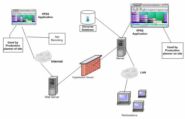
Figure 15: VPSS System Architecture
3.3.2 What are Smart Clients?
Smart Clients are a combination of the powerful rich clients which
contain many features and web-based applications which are a lot more
efficient. It provides a rich user
interface that is powerful and allows manipulation of data on the local
computer but also allowing better options to connection to networks and the
internet. They are designed for improved
speed and performance from applications, which is aimed at making the users
more productive.
There are many features of smart client technology that suit the needs
of the VPSS application and they are becoming more technologically advanced. The
following are the characteristics of smart client technology and reasons why we
use smart clients:
High fidelity
It allows for the use of the latest graphics and user interface technology,
you can customize for each user based on the context of the customization. (Colours
of work orders and backgrounds of work centres can be restored)
Connection intelligence
It allows the users of our application to work online or offline by making
use the local data caching ability. Furthermore, as we have combined this
technology with .Net remoting, it allows the data that has been manipulated to
be saved.
Information centric
Smart clients
are based on the information, which is why data access is loosely coupled and
is flexible, data about work orders and work centres are easy to retrieve,
cache and post.
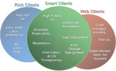
Figure 16: Features of a
smart client
3.3.3 How .Net Remoting Works
It must be noted here that the following
explanation of .Net remoting extensively uses information from Computer Science
335: Disturbed Objects and Web Services.
.NET Remoting components
consist of server, client and a proxy of each server on each client. A proxy is
created by running the server first and then uses the soapsuds command to
generate automatically.
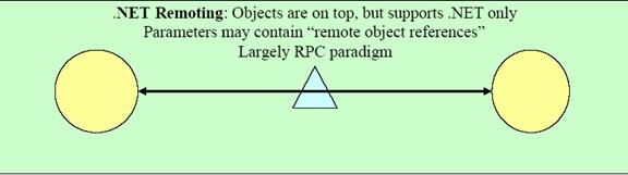
Figure 17: .Net remoting
The server inherits from the
class MarshalByRefObjects. A MarshalByRefObject
is a remote object that runs on the server and accepts method calls from the
client. Its data is stored in the server’s memory and its methods executed in
the server’s AppDomain. Instead of passing around a variable that points to an
object of this type, in reality only a pointer-like construct—called an
ObjRef—is passed around. Contrary to common pointers, this ObjRef does not
contain the memory address, rather the server name/IP address and an object
identity that identifies exactly one object of the many that are probably
running on the server.
MarshalByRefObject
is categorized into 2 groups, Server-Activated-Objects (SAO) and
Client-Activate-Objects (CAO).
SAO:
Server-activated objects are
somewhat comparable to classic stateless Web Services. When a client requests a
reference to a SAO, no message will travel to the server. Only when methods are
called on this remote reference will the server be notified.
Depending on the
configuration of its objects, the server then decides whether a new instance
will be created or an existing object will be reused. SAOs can be marked as
either Singleton or SingleCall. In the first case, one instance
serves the requests of all clients in a multithreaded fashion. When using
objects in SingleCall mode, as the name implies, a new object will be created
for each request and destroyed afterwards.
CAO:
A client-activated object
(CAO) behaves mostly the same way as does a “normal” .NET object (or a COM
object). When a creation request on the client is encountered (using
Activator.CreateInstance() or the New operator), an activation message is sent
to the server, where a remote object is created. On the client a proxy that
holds the ObjRef to the server object is created like it is with SAOs. A
client-activated object’s lifetime is managed by the same lifetime service used
by SAOs.
CAOs are so-called stateful
objects; an instance variable that has been set by the client can be retrieved
again and will contain the correct value. These objects will store state
information from one method call to the other. CAOs are explicitly created by
the client, so they can have distinct constructors like normal .NET objects do.
For our Visual Production
Scheduling System we will use Client-activated objects (CAOs) which will have a
lifetime that is managed by the calling application domain. Therefore, as long
as the web client requires a connection to the database, the server will hold
onto it.
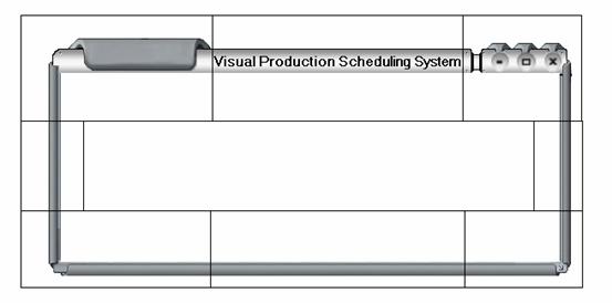
3.3.4 Explanation to Creating Skinned Applications
There are two classes that
we are required to understand. The first is the frmBorder class which handles
all the resizing and movement of the application and is where the customized
skin images are stored. The second class is frmMain, which holds a main menu
and contains all the controls the user will interact with. Both frmBorder and
frmMain inherits from the standard Windows.Forms class.
The frmBorder form is
separated into 8 different sections, top left, top middle, top right, middle
left, bottom left, middle bottom, bottom right, and right middle. Each section
is a panel which contains a portion of the skinned border. All the middle
sections have their DockStyle set to “fill” while all others are docked to
their respective corner, (e.g. Top left is docked to the left). The important
thing to note is that there is a further 4 underlying panels, top, left, right
and bottom. The top panel contains the three top sections, while the bottom
panel contains the bottom three sections. Left and right contain their
respective sections.
The following image shows
the 8 different sections of frmBorder:
3 1
![]()
5 8 7 4
![]()
![]()
![]()
![]()
![]()
![]()
![]()
6
![]()
1: Top Left (Dock Left)
2: Top Middle (Dock Fill)
3: Top Right (Dock Right)
4: Middle Right (Dock Fill)
5: Bottom Right (Dock Right)
6: Bottom Middle (Dock Fill)
7: Bottom Left (Dock Left)
8: Middle Left (Dock Fill)
FrmBorder also handles
detecting whether the user has moved the mouse into a place where he/she may
resize the form. When the user is on a border edge, frmBorder will detect this
and appropriately change the cursor. When the user holds the mouse and drags to
resize when he/she is at a border edge, this frmBorder will draw a dotted
rectangle which is an outline of the resized rectangle. Furthermore, as the
user moves, the program will detect whether the user is attempting to resize
smaller than the minimum size, if this is the case, the dotted line will not be
drawn any smaller. That is, the smallest dotted outline that the application
may paint is the minimum size of the program. When the user releases their
mouse, the program will expand or shrink the application to fill the dotted
line and change the size and location of frmMain appropriately.
The most important aspect of
frmMain is that is contains the main menu and also all controls that the user
will interact with.
In order to create new
skins, all the developer has to do is cut a skin into the 8 different sections
shown and modify some of the mouse events used for detecting the border edge.
![]()
Figure 19: Class Package Diagram
The package diagram has been
used instead of a sub system diagram as it allows better understanding of the
architecture of the VPSS application. A
brief description for each package is given on the following pages along with in
depth descriptions of the associated classes.
![]()
3.5.1 Design
Decisions
![]() This package uses
data that is retrieved from the Data Management package. However it is
completely independent and does not know whether the data is being retrieved
locally, over a LAN or via the internet.
This package uses
data that is retrieved from the Data Management package. However it is
completely independent and does not know whether the data is being retrieved
locally, over a LAN or via the internet.
![]() Extensive use of
inheritance to allow for reuse of code.
Extensive use of
inheritance to allow for reuse of code.
![]() Inheriting common
controls and overriding events in order to create a completely customized look
and feel complete with the ability to create gradient backgrounds.
Inheriting common
controls and overriding events in order to create a completely customized look
and feel complete with the ability to create gradient backgrounds.
![]() Highly modular.
Each class handles its own repainting and events.
Highly modular.
Each class handles its own repainting and events.
![]() Hierarchal
structure – classes are structured in a hierarchal fashion so that one class
contains a collection of another class which also contains a collection of
another class etc. This provides a resemblance to how data is represented in
Beacon.
Hierarchal
structure – classes are structured in a hierarchal fashion so that one class
contains a collection of another class which also contains a collection of
another class etc. This provides a resemblance to how data is represented in
Beacon.
3.5.2 Overview
This package consists of
classes that handle the display of the production schedule onto the
screen. The functionality of having two
views, Shadowboard and Grid are contained within this package. Their super
class, CommonView that contains functionalities that are common across both the
views is also defined within this package.
All controls that represent data that is retrieved from the Data
Management Package are also contained here.
3.5.3 Class Descriptions
![]() CommonView - This is an abstract super class which inherits
from the common panel control and provides functionality which is common for
both the shadowViewPanel and gridViewPanel class. As both views inherit from
this class, it allows switching between the views to occur easily. The methods
that are used by both classes are stored here; this includes the resizing code
which allows the width of each date to be changed as well as the height of each
work centre. This class is also responsible for calculating overload and
painting this to the screen. The data that is retrieved from the database is
also stored here.
CommonView - This is an abstract super class which inherits
from the common panel control and provides functionality which is common for
both the shadowViewPanel and gridViewPanel class. As both views inherit from
this class, it allows switching between the views to occur easily. The methods
that are used by both classes are stored here; this includes the resizing code
which allows the width of each date to be changed as well as the height of each
work centre. This class is also responsible for calculating overload and
painting this to the screen. The data that is retrieved from the database is
also stored here.
![]() GridViewPanel
-This class provides the
functionality that is unique to grid view. As discussed previously, grid view allows
the user to see the production schedule over a larger period of time and in a
more summarized form. This class is responsible for showing the production
schedule in days, weeks and months by calculating where each work order
belongs. The loading of the work orders into grid view differs slightly to that
of shadowboard view.
GridViewPanel
-This class provides the
functionality that is unique to grid view. As discussed previously, grid view allows
the user to see the production schedule over a larger period of time and in a
more summarized form. This class is responsible for showing the production
schedule in days, weeks and months by calculating where each work order
belongs. The loading of the work orders into grid view differs slightly to that
of shadowboard view.
![]() UnderlyingWorkCentres
– This class represents one
entire work centre. Contained within this class is a hash table which
represents all the days that belongs to this work centre. If the user has
chosen to hide this work centre, it will store the previous height so that when
the user expands, it will expand to the previous height which creates a higher
quality application rather than snapping back to a default height.
UnderlyingWorkCentres
– This class represents one
entire work centre. Contained within this class is a hash table which
represents all the days that belongs to this work centre. If the user has
chosen to hide this work centre, it will store the previous height so that when
the user expands, it will expand to the previous height which creates a higher
quality application rather than snapping back to a default height.
![]() WorkCentre - A work centre can have capacity across many days.
The WorkCentre class represents one time period (day, week or month). Hence,
the work centre class may contain 0 or many work orders. Every work order that
belongs to one instance of the WorkCentre class is stored within a hash table
with the date as the key in order to allow for quick data retrieval. This class
inherits the graidentPictureBox custom control so that it can paint a gradient
background, have the ability to autoscroll as well as being able to hold other
controls. Hence, this class holds all the work orders that belong to a
particular work centre on a particular date. Most importantly, this class
handles the ability to drag and drop a work order onto a different date.
WorkCentre - A work centre can have capacity across many days.
The WorkCentre class represents one time period (day, week or month). Hence,
the work centre class may contain 0 or many work orders. Every work order that
belongs to one instance of the WorkCentre class is stored within a hash table
with the date as the key in order to allow for quick data retrieval. This class
inherits the graidentPictureBox custom control so that it can paint a gradient
background, have the ability to autoscroll as well as being able to hold other
controls. Hence, this class holds all the work orders that belong to a
particular work centre on a particular date. Most importantly, this class
handles the ability to drag and drop a work order onto a different date.
![]() WorkOrder – This class provides the functionality of holding
all relevant information that relates to one work order. Each work order is
custom painted and supports the ability of a gradient background.
WorkOrder – This class provides the functionality of holding
all relevant information that relates to one work order. Each work order is
custom painted and supports the ability of a gradient background.
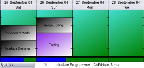
1) This is one instance of a work order object
2) This is one instance of a work centre object
As seen in the above
diagram, each work centre may contain 0 or more work orders. Beneath the row of
work centres, is an instance of underlyingWorkCentres. Gridview panel may
consist of 1 or more underlyingWorkCentres.
![]()
3.6.1 Design
Decisions
![]() Custom skinned
border to create a visually appealing application.
Custom skinned
border to create a visually appealing application.
![]() Large clean icons
that displays common features that the user uses frequently. When the user
mouseovers an icon, the system responds by producing a subtle animation that
informs the user that he has scrolled over the icon.
Large clean icons
that displays common features that the user uses frequently. When the user
mouseovers an icon, the system responds by producing a subtle animation that
informs the user that he has scrolled over the icon.
![]() Manual resizing
with transparent lines to represent what the application will look like instead
of resizing on-the-fly in order to remove any lag associated with resizing
controls and repainting them. This provides for a far nicer look and feel to
the application
Manual resizing
with transparent lines to represent what the application will look like instead
of resizing on-the-fly in order to remove any lag associated with resizing
controls and repainting them. This provides for a far nicer look and feel to
the application
3.6.2 Overview
This package encompasses all
the classes that handle the creation of a customized skinned application.
3.6.3 Class Descriptions
frmBorder –This class handles all the resizing and movement of
the application and is where the customized skin images are stored. This class
handles the detection of when the user may resize the application (user is on a
border edge) and when he/she is in a suitable position, also handles the custom
resize procedures as well. Resizing will not distort the image in any way as
only the middle sections of the skin will be expanded. This class is the owner
of frmMain.
frmMain – Container form for shadowViewPanel or
gridViewPanel. This is also the class that creates the toolbar and main menu.
frmLibrary – Provides shared access to both frmMain and
frmBorder throughout the application. Future developers can now refer to
frmMain and frmBorder easily without passing instances of it back and forth.

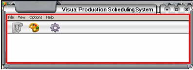
Figure 21: VPSSApplication
Package
1) Represents an instance of the frmBorder class
2) The area inside the red rectangle represents an
instance of the frmMain class
![]()
3.7.1 Design Decisions
![]() We have created a
custom control to paint a gradient background instead of using bitmaps in order
to dramatically save memory resources.
We have created a
custom control to paint a gradient background instead of using bitmaps in order
to dramatically save memory resources.
![]() Both the forms used to modify colour settings are slightly
different but near identical to ensure a consistent flow through the program.
Both the forms used to modify colour settings are slightly
different but near identical to ensure a consistent flow through the program.
3.7.2 Overview
This package contains all
the classes that relate to providing the user the ability to change colour
settings in the VPSS application. This
includes allowing customization of work order colors, work centre background
colors and the load indicator.
3.7.3 Class Descriptions
![]() GradientPictureBox
– This class inherits from the
common control class and overwrites the paint method so that it allows painting
of gradient backgrounds.
GradientPictureBox
– This class inherits from the
common control class and overwrites the paint method so that it allows painting
of gradient backgrounds.
![]() ColorBox – This is a windows form class that provides the
functionality of allowing the user to change the color of the work centre
backgrounds. User may select up to two different colors and the gradient style
ColorBox – This is a windows form class that provides the
functionality of allowing the user to change the color of the work centre
backgrounds. User may select up to two different colors and the gradient style
![]()
 frmWorkOrder – This form provides the user with the ability to modify the work order
colors. There are three different work order types that can be modified and
each type allows up to two color selections and a gradient style.
frmWorkOrder – This form provides the user with the ability to modify the work order
colors. There are three different work order types that can be modified and
each type allows up to two color selections and a gradient style.

3.8.1 Design Decisions
![]() Colour settings
will be loaded at start-up from the database to a shared class that is
accessible throughout the project. If no values are found in the database,
default ones are used.
Colour settings
will be loaded at start-up from the database to a shared class that is
accessible throughout the project. If no values are found in the database,
default ones are used.
3.8.2 Overview
This package consists of
classes that specialize in retrieving and storing information to and from the
database. As all the information
required by the VPSS application is stored within Beacon, it needs to be
extracted and organized into a manner which allows the application to display
it.
3.8.3 Class Descriptions
![]() ColorSettings
– This is a public accessible
shared class which stores all the custom color settings. It is populated from
the database at load up, if there are previous settings, the defaults are
loaded up
ColorSettings
– This is a public accessible
shared class which stores all the custom color settings. It is populated from
the database at load up, if there are previous settings, the defaults are
loaded up
![]() CRP – This class handles all calls to and from the
database. It consists of methods which call predefined sub routines to extract
the required data from Beacon. Furthermore, it also has methods which modify
fields in the database to support the ability to save personalized settings and
work order dates that have been changed due to a drag and drop operation.
CRP – This class handles all calls to and from the
database. It consists of methods which call predefined sub routines to extract
the required data from Beacon. Furthermore, it also has methods which modify
fields in the database to support the ability to save personalized settings and
work order dates that have been changed due to a drag and drop operation.
![]()
3.9.1 Design
Decisions
![]() This class is
inherited directly from the Beacon.dll and therefore we did not make any design
decisions relating to this package
This class is
inherited directly from the Beacon.dll and therefore we did not make any design
decisions relating to this package
3.9.2 Overview
This package consists of the
class that is called when Beacon invokes the VPSS application to start up from
its main menu. The session is passed on
to this class and the application starts up with the connection established to
the Beacon system.
3.9.3 Class Descriptions
![]() ProcessSession
– This class is responsible for
retrieving the connection created to the Beacon System. It is instantiated via
Beacon Systems main menu.
ProcessSession
– This class is responsible for
retrieving the connection created to the Beacon System. It is instantiated via
Beacon Systems main menu.
![]()
3.10.1 Design Decisions
![]() This class is also
inherited directly from the Beacon.dll and therefore we did not make any design
decisions relating to this package as well.
This class is also
inherited directly from the Beacon.dll and therefore we did not make any design
decisions relating to this package as well.
3.10.2 Overview
This is package contains the
class that passes information about Beacon’s main window to the Visual
Production Scheduling System.
3.10.3 Class Descriptions
![]() frmBeaconFormBase
– This is the form that
frmBorder inherits from. Its main job is to detect where the Beacon command
window is so that we can position our application correctly. This class also
handles the closing of our application and reopens the Beacon command window again.
frmBeaconFormBase
– This is the form that
frmBorder inherits from. Its main job is to detect where the Beacon command
window is so that we can position our application correctly. This class also
handles the closing of our application and reopens the Beacon command window again.
![]()
The VPSS application is
divided into layers beginning with the user interface layer, followed by the
problem domain layer, data management and the System architecture layer.
Figure 23: VPSS Application Layer Diagram
The User Interface layer contains classes associated with the idea of
view and controller. The purpose of this
layer is to keep the user interface separate from the problem domain, which
allows for greater portability of the system.
The frmMain class can be seen as the controller, which sends messages to
the classes in the problem domain layer and telling the classes what actions
needs to be taken.
The data management layer deals with the persistence of objects which
are contained within the system and in the case of the VPSS application it’s
the persistence of the information relating to work orders and work centres
displayed. All the issues of this layer
such as storage format and storage optimization have already been addressed as
we are integrating an application into an existing system. The two classes within this layer deal with
extraction and persistence of data into the Universe database.
The problem domain layer deals with what the application is trying to
model or what problem/issues the application is being created to solve. For the VPSS application we are trying to
model the task of production scheduling and the classes within this layer
directly deals with production scheduling.
The system architecture layer deals with how our application executes
on specific computers and networks. The
Beacon system communicates with our application and passes the session to the
class within this layer, which is then used to execute VPSS.
![]()
3.12.1 Standards
Prior to the start of the
programming of the VPSS application, coding standards were set out for the
development of the application.
Standards need to be in place, so everyone working on the development
stage can easily understand the code.
Also it is helpful for future developers who may perform maintenance
tasks, fixing bugs or adding additional features.
For this reason, it was
decided by the team that generally accepted coding standards used by Microsoft
and other institutions is used to develop the VPSS application. As defined by Microsoft, the coding standards
are divided into three sections; naming, comments and format.
![]() Naming
Naming
The
naming standards relate to how the variables and methods are named, it is very
important that names are given appropriately as it helps with the logical flow
of the application and at the same time reduces ambiguity and complexity. The following example clearly shows the
importance of good naming conventions:
the naming of this method, fillDateAndNameArray(), gives an better
insight of what this method is doing rather than naming it fillArray(). The aim has been to make the names meaningful
while keeping it as short as possible.
The
naming of variables also has a distinctive pattern, ever variable is prefixed
by the type of the variable. An example of this is a variable that is an integer
and relates to a height of a column, the name given will be intColumnHeight. This allows the developer to get an
indication of what the variable is, how and why it is being used in the
particular line of code.
![]() Comments
Comments
Comments
within the source code is very important even though methods and variables have
been named in a manner that allows ease of understanding and external documents
have been prepared such as help files and technical documents. Each method in the VPSS source code has a
written description which describes the purpose and how the method is
used. In some instances just having a
description for the method may not be enough to understand the lines of code
within the method. Therefore to help
future developers, every single line of code will have brief comments
associated with it. This conforms to Walstan Systems requirement of a line of
comment on every line of code.
![]() Format
Format
For
ease of understanding it is important to organize the code in the manner that makes
it is easily readable, this relates to the use of indentation and spacing
between lines of code. Each indentation
is two spaces across and spacing is the normal size. This helps to minimize the length of a line
of code which is ideal for printing.
The team has met all coding
requirements set by Walstan at the beginning of this project. This includes a
comment on every line of code, indentation should be set to 2 spaces across to
allow for easy printing, and comments should be placed on column 49 if this is
possible.
3.12.2
Global Map of Code
 The following diagram shows where classes belong and
who owns them. It provide easy understanding for future developers to see which
classes interact with each other and how many instances of a class may be or
must be created.
The following diagram shows where classes belong and
who owns them. It provide easy understanding for future developers to see which
classes interact with each other and how many instances of a class may be or
must be created.
Figure 24: Global Map of Code
As shown in the previous
diagram, the structure of the code is very hierarchal. FrmBorder creates and
owns an instance of frmMain which in turn creates the CRP class used to retrieve
the data from Beacon. Furthermore, frmMain may instantiate a color box when the
user requests to modify the background color and can also instantiate
frmWorkOrder upon the users request to modify a work order color. Most
importantly, frmMain contains an instance of CommonView which is the main panel
that holds all the information we display. When a CommonView object is created,
it automatically creates an instance of the ColorSettings class which then
attempts to retrieve the users previously saved color settings. If it fails in
doing so, the default colors will be loaded in. CommonView must contain 1 or
more UnderlyingWorkCentre objects which represents one entire work centre over
a period of time. UnderlyingWorkCentre must then instantiate 1 or more WorkCentre
objects that inherits from the GraidentPictureBox class and represents a single
time period and belongs to a single UnderlyingWorkCentre. Keeping with our
hierarchal structure, a Work Centre object may contain 0 or more WorkOrder
objects which contains the main information we want to convey to the user.
3.12.3
Code Tree
The hierarchal nature
of the code creates a tree like diagram. Below is a tree structure which shows
what our program may look like. Only the main classes that are the must important
and contain the data to display are shown.
Figure 25: Code tree
![]()
3.13.1 Introduction
The design of the user
interface for the Visual Production Scheduling System is the primary objective
of our project. As the interface is the gateway between the user and the
application, it is fundamental to the success of our project to make the
interface attractive and aesthetically appealing, simple to use whilst
minimizing the effort the user has to make in order to accomplish a task, such
as scheduling a work order.
The screen flow diagram has
been included which provides a model for the interactions of the user with the
VPSS application and it provides a high level overview of the user interface
which allows for a quick understanding of how the application works.
3.13.2 Screen Flow Documentation
Shown in figure 26 is the screen flow diagram
which illustrates the screen sequences for the Visual Production Scheduling
System. The following is a brief description of each screen and its purpose.
![]() Login Screen
Login Screen
This is the Beacon System
login screen; it requests the user to enter their login name and password
before they are able to access the main Beacon menu.
Purpose – Prevent
unauthorised access to the application and also to allow personalised settings
to be kept for each user.
![]() Beacon Main Menu
Beacon Main Menu
This is the access point to
the Visual Production Scheduling System. It is from this window that the user
will enter in the command to load the application.
Purpose – Allow the user
to load the program.
![]() Loading Progress screen
Loading Progress screen
This
is a temporary loading screen that is displayed to inform the user the
application is loading up. The main
purpose is to give the user feedback and stop the user from mistakenly
executing the program multiple times.
Purpose – To provide
feedback to the user that the application is currently loading.
![]() Production Schedule
Production Schedule
This
is the main screen of the application and can be either shadowboard view or
grid view. This screen shows all the information that we have extracted from
the database in a graphical format.
Purpose – To display the
graphical representation of the production schedule to the user.
![]() Change Background Color Dialog
Change Background Color Dialog
This
is the dialog box that is displayed when the user requests to make a change to
the color that is used to paint the background. It is from here that the user
may modify the color and gradient style of the background.
Purpose – To allow the
user to customize the colour of the work centre background.
![]() Change Work Order Color Dialog
Change Work Order Color Dialog
This
is the dialog box that is displayed when the user wants to make changes to the color
used to distinguish between the three different work order types. The user may modify the color and gradient
style for each type of work order.
Purpose – To allow the user to
customize the colour of each work order type.
![]() Print Schedule Dialog
Print Schedule Dialog
When
the user requests to print the schedule, this dialog will appear to request the
user for parameters which will be used to print the schedule. (e.g. time period
to print for, work centres to print for)
Purpose – Request
information from the user about what he/she wishes to print.
![]() Print Preview
Print Preview
Allows
the user to see how the production schedule will look when printing. This helps
to make efficient use of resources as users now get a chance to see what they
are about to print and can modify the settings if he/she is not happy with the
current look.
Purpose – To allow the
user to visualize what the document will look like when printed.
![]() Switching Views Loading Screen
Switching Views Loading Screen
This
is another temporary loading screen that is displayed to inform the user that
the application is switching from shadowboard view to grid view or vice
versa. This is done to keep the user
updated on the status of the switch from the different views.
Purpose – To provide the
user with feedback about the current loading status of the program.
3.13.3 Screen Flow Diagram
Figure 26: VPSS Screen Flow Diagram
![]()
3.14.1
Introduction
The aim of the Visual Production Scheduling System, as the name
suggests, is to create a graphical user interface to present the
information stored in the UniVerse database in a graphical format that is easy
for the user to absorb and comprehend in the shortest amount of time
possible. Taking into account of this
simple goal, the design of the user interface has been created based on the
principles of interface design set out by Microsoft. Listed below are the
principles that we have adhered to and an explanation of how the Visual
Production Scheduling System has implemented these principals.
3.14.2
Directness
This principle states that the
users should be able to directly manipulate objects that represent information
in an application. Information
represented visually help reduce the mental work done by the user trying to
understand the information. Metaphors
that are familiar provide intuitive and direct interface for the users to
perform their tasks.
In the VPSS application, the work orders are
displayed as rectangular shapes that can be dragged and dropped onto different
time periods. This is direct manipulation of information which is visually easy
to follow. Each row in the application
represents a work centre and each column represents a time period. The work
orders are displayed to scale depending on the amount of hours it takes to
complete the work order. Furthermore, an overload indicator is provided at the
bottom of each time period to show how much capacity remains for that period of
time.
3.14.3 User in
Charge
This principle states that
the user should always feel that they are in charge of the application. This means all the actions should be
initiated by the user and not by the application, also as individual
preferences may differ, it should be possible for the user to personalize the
settings of the application such as colours, height and width. Furthermore the
application should be interactive and responsive to the user as much as
possible.
The VPSS application fulfills
this requirement as after the initial start up of the application, all the
features of the application is initiated by the user e.g. resize the form of
the application, switch between the views etc. This also means the application
is responsive to the user commands and not vice versa. The user is also able to personalize the
color settings of the application which is then saved so that upon a future
login, the user does not have to manually set the colors again.
3.14.4 Consistency
This principle states that
features and functions should be consistent throughout the application. This allows the user to transfer knowledge to
new tasks so that it can be learnt in the shortest amount of time. The interface should be familiar and
predictable which allows the user to get accustomed to the application more
quickly. Consistency is required in all
areas, naming conventions, font, size, color, visual presentation of
information, operational behaviour etc.
Consistency has been
maintained throughout the VPSS application, an example of this is the size and
font of the dates displayed in both grid view and shadowboard view. The manner in which information is displayed
and the functions in both views are also consistent, this provides a near
identical look between the two views. Work order colors and work centre
backgrounds remain the same when switching between views as well as the manner
in which work orders are displayed.
3.14.5
Forgiveness
This
principle states that users like to learn a new application by trial and error
and the application should accommodate for this and give warnings to users
about potential situations where irreversible changes might be made.
The VPSS will be able to handle mistakes made by
users, without ending up with results that obstructs the production planner
from completing their tasks. We have
designed many warning message boxes which will alert the user if he/she decides
to perform a dangerous operation and from here, the user may cancel the
operation.
3.14.6 Simplicity
This principle states that
the design of the interface should be simple in terms of being easy to use and
learn. It should allow the user access to all the functions of the application
without over complicating the design.
This can be done by reducing the amount of information displayed at one
time, which helps reduce cluttering and information overload.
The VPSS user interface has
been designed to keep the amount of information displayed at one time to a
minimum. Only the most relevant information is displayed, users may see more
detailed information about a particular work order by hovering over the work
order and a tool tip will be displayed. Instead
of displaying the values of the capacity and load on the machine, it has been
drawn graphically for ease of understanding of the information. This method of
showing detailed information only when it is required is called progressive
disclosure.
3.14.7 Aesthetics
This principle states that
the visual design of an application contributes to presenting information in an
effective manner to the user. Every
element displayed on screen competes for the users’ attention; therefore the
elements need to be displayed in manner that aids the user to understand the
information displayed. These elements
communicate the information in a manner that should leave an impression on the
user.
The VPSS application is a
graphical user interface and the emphasis has been creating graphical
representations of data in a colorful format which communicates the production
schedule in an effective manner.
Emphasis has been placed on using vibrant colours to distinguish between
objects displayed on the interface.
3.14.8
Feedback
Feedback is very important to users when using an application as
feedback is the only way the computer can communicate to the users. When +users perform an operation and do not
receive immediate feedback, they are likely to keep repeating that operation until
feedback is given that the task is being completed.
The VPSS application
provides feedback to users where actions performed are expected to take a small
period of time to complete via a progress bar.
Feedback is also given when the application loads up for the first time
and information is being processed to be displayed. Cursor changes also occur when the user is at
the border of the application, which informs them that the application border
can be resized. Furthermore, when the user moves over an icon that can be
interacted with, the icon will produce a subtle animation to inform the user
that he/she may click the icon.
3.15.1
Introduction
This section of the technical document will cover the environment that
the system requires to run on. The hardware and software that is required for
the system to function is stated here along with the technologies that have
been used to create the Visual Production Scheduling System.
3.15.2
Hardware Environment
In order for the Visual Production Scheduling System to operate, it
requires three different areas of hardware, the client, the connection used to
communicate between the client and the server, and the server which holds all
the required data.
1) Client
This is the machine which will contain the Visual Production Scheduling
System. As the program was created using Vb.Net, the client machine must have
the .Net framework installed. The processing speed of this computer is not of
high importance as our program has been designed to run on low spec computers
at a reasonable speed.
2) Communications Network
There must exist a connection between the client and the server, this
may be over a LAN or over the internet.
3) Server
The server is the machine which will store the required data that is
required by our application. The machine must have Beacon for Business running.
3.15.3
Software Environment
The Visual Production Scheduling System offers full compatibility on any
machine running Windows 2000 Server, Windows XP home or Professional edition
with the .Net Framework installed. While it is a high possibility that this
application will run on other Windows operating systems, it has not been tested
by the team.
3.15.4
Technologies Used
The software tools which have helped to create the Visual Production
Scheduling System are briefly described below:

Microsoft .NET Framework
The .NET Framework is a
multi-language environment for building, deploying, and running XML Web
services and applications. It consists of three main parts:
Common
Language Runtime While
the component is running, the runtime is responsible for managing memory
allocation, starting up and stopping threads and processes, and enforcing
security policy, as well as satisfying any dependencies that the component might
have on other components.
Unified
programming classes The
framework provides developers with a unified, object-oriented, hierarchical,
and extensible set of class libraries (APIs). By creating a common set of APIs across
s all programming languages, the common language runtime enables cross-language
inheritance, error handling, and debugging.
![]() To program in .NET framework, the best tool to use is
Visual Studio .NET. Visual Studio .NET is a complete set of development
tools for building ASP Web applications, XML Web services, desktop
applications, and mobile applications. Visual Basic .NET, Visual
C++ .NET, Visual C# .NET, and Visual J# .NET all use the same
integrated development environment (IDE), which allows them to share tools and
facilitates in the creation of mixed-language solutions. In addition, these
languages leverage the functionality of the .NET Framework, which provides
access to key technologies that simplify the development of ASP Web
applications and XML Web services. VPSS will be written entirely in VB.NET.
To program in .NET framework, the best tool to use is
Visual Studio .NET. Visual Studio .NET is a complete set of development
tools for building ASP Web applications, XML Web services, desktop
applications, and mobile applications. Visual Basic .NET, Visual
C++ .NET, Visual C# .NET, and Visual J# .NET all use the same
integrated development environment (IDE), which allows them to share tools and
facilitates in the creation of mixed-language solutions. In addition, these
languages leverage the functionality of the .NET Framework, which provides
access to key technologies that simplify the development of ASP Web
applications and XML Web services. VPSS will be written entirely in VB.NET.
![]()
![]()
The MSDN Library is an
essential resource for developers using Microsoft tools, products, and
technologies. It contains a bounty of technical programming information,
including sample code, documentation, technical articles, and reference guides.
Also, the MSDN magazines that are updated regularly are also extremely helpful.
It publishes the new discovery or inventions of other .NET researchers.
![]()
We have made full use of the
tools available in Microsoft Office. Work 2003 has been used extensively
throughout the project to help with the documentation of the system. Project
has allowed the team to schedule dates for milestone versions of the program to
be completed. The application has shown the projects progress during it development
duration lifecycle.
![]() Windows Server is the most productive infrastructure
platform for powering connected applications, networks, and Web services from
the workgroup to the data center. Easy to deploy, manage, and use, Windows
Server helps to build a secure IT infrastructure that provides a powerful
application platform for quickly building connected solutions and an
information worker infrastructure for enhanced communication and collaboration
anytime and anywhere. The team has used Windows Server 2000 to ensure full
compatibility with the current Beacon System.
Windows Server is the most productive infrastructure
platform for powering connected applications, networks, and Web services from
the workgroup to the data center. Easy to deploy, manage, and use, Windows
Server helps to build a secure IT infrastructure that provides a powerful
application platform for quickly building connected solutions and an
information worker infrastructure for enhanced communication and collaboration
anytime and anywhere. The team has used Windows Server 2000 to ensure full
compatibility with the current Beacon System.

UniVerse brings the
performance and scalability features of enterprise relational databases to Beacon
System. In addition to cross-platform strengths like the advanced query
optimizer, UniVerse leverages Windows-specific capabilities to achieve the
maximum performance on the platform. IBM UniVerse database is well positioned
to take advantage of the ever increasing capabilities of the Windows and Intel
platform both in terms of scale up and scale out capabilities. UniVerse also
provides the option of achieving scalability through shared nothing clustering.
Therefore Walstan Systems Ltd decided to carry on using IBM Universe Database
as the database of VPSS and the whole Beacon.
3.15.5
Development Environment
|
Server Machine |
Development Machine Intel Pentium 4 – 2.4
Gigahertz 512 Megabytes DDR RAM 80 Gigabytes Hard Drive
Disk Microsoft Windows XP
Professional |
![]()
Our final system will be
flexible enough to be expanded easily. We have identified three possible
expansions which are as follows:
3.16.1 Create New Work Orders
The production planner can
only view existing work orders which have already been created in Beacon. Future enhancement of the application could
be the ability to create new work orders from within the Visual Production
Scheduling System.
3.16.2 Hypothetical Production Schedule
At present, when the
production planner makes changes to the production schedule it is immediately updated
to the database. A further enhancement
of the VPSS application could be the ability to allow the user to modify the
data without changes being saved back to the database.
3.16.3 Personalised settings
Currently the user can only
save the colour settings of the background, work order and load indicator. A
possible enhancement may be to allow further customizations to be saved, such as
the width of the columns and the height of a particular work centre after a
user has resized.
3.16.4 Define/Change Work Centres
Our proposed system only
retrieves the information about work centres and does not allow the user to
create their own work centres with their own specifications. We could extend
the system by allowing the users to define and change the settings of a new or
existing work centre. If this enhancement is undertaken together with the
previous Create New Work Order enhancement, then this program will be powerful
enough to run as a standalone application without relying being so dependent on
Beacon.
![]()
![]() IMPLEMENTATION AND TESTING
IMPLEMENTATION AND TESTING
![]() Development
Approach
Development
Approach
![]() Project
Implementation phases
Project
Implementation phases
![]() Testing
Testing
4.1.1 Feature
Driven Development
The emphasis has
been on creating a system which encompasses certain functionality or features.
For this reason the development of the application has been feature driven with
the most important and fundamental features developed first. The program was broken down into separate versions
with each version building on the features already in place from the previous
version. The roadmap on the following page shows the breakdown of each version:
4.1.2 Road Map
Version 0.1 -
Initial Release
- Create a custom skinned
application with a borderless form
- Display work centre panels
- Display date panel
- Display a scale which shows
the number of hours available on a particular day.
Version 0.2
- Allow resizing of date column
(width)
- Allow resizing of work centre
row (height)
- Allow resizing of the whole
application without distortion to the skin
- Support the ability to send
to tray
Version 0.3
- Allow backgrounds to be
painted in gradient colours
- Allow work centres to be
hidden and shown on command by pressing a button
- Create rollover images for
the buttons used to hide/show the work centre
Version 0.4
- Integrate into beacon
- Extract information from
beacon
- Draw transparent lines when
resizing rather than resizing on-the-fly to improve performance
- Display work orders on the
application
- Create two separate and different
views (shadowboard, grid)
Version 0.5
- Implement drag and drop
ability to manipulate work orders
- Support gradient colour for
work orders
- Implement full screen version
- Update GUI
- Polish and clean up
Version 0.6
- Allow users to change the
colours of the background and work orders
- Create help files
- Internet enabled
- Tool tips to be displayed
when the cursor is placed over a work order, the tool tip contains
detailed information relating to that work order.
- Implement the load indicator
which shows the capacity of a work centre on a particular day and how much
of it has been used.
Version 0.7
- Save information back to
database.
Version 0.8
- Implement security features –
allow views depending of role of user
- Save the colour settings back
to the database for personalization.
- Create icons for buttons
- Create a toolbar to display
icons of features that are commonly used
Version 0.9
- Full bug testing version
- Implement the printing of
details
Version 1.0
·
Release
to client
![]()
4.2.1 Prototype
1: XML Based Prototype
The
implementation of the user interface was the first step to the creation of the
Visual Production Scheduling System. The
purpose of the application is to represent the information stored within Beacon
into graphical format. Therefore, this
module consisted of creating the interface that was designed at the analysis
phase of this project.
This prototype consisted
of the creation of the user interface without displaying any data from the
Universe database. Instead, we used fake data from a XML file to represent the
data that was to come out of the database.
4.2.2 Prototype
2: LAN Prototype
In this
prototype the VPSS application was integrated into the Beacon system and data
was being extracted from the Universe database.
On completion of this prototype, the VPSS application was functional
over the Local Area Network and could be accessed from multiple workstations.
4.2.3 Prototype
3: Internet Prototype
This prototype
aimed to create a fully working application that was functional over the
internet and through firewalls. This will provide the end user with the added
ability to access the application from anywhere with an internet connection.
Furthermore, this prototype will utilize smart client technology to extend the
abilities of the previous prototypes.
![]()
4.3.1 Testing
Approach
Testing of the software
that has been created is an essential part of the software development life
cycle. The procedures used in testing
aims to identify bugs that could have crept into the system while programming
and would be very costly to remove once the system has been implemented and
after the project team hands over the system to Walstan.
Some of the testing procedures
which we used are listed below:
![]() White Box testing: Open the source file and read through the code line by line and see
whether there are any logic errors or syntax errors. For example, assume an
exception occurs in line 578 and 623 and 634, go to line 578 first and find out
whether the fault occurs in here or in line 623 which was called by line 578,
and so on.
White Box testing: Open the source file and read through the code line by line and see
whether there are any logic errors or syntax errors. For example, assume an
exception occurs in line 578 and 623 and 634, go to line 578 first and find out
whether the fault occurs in here or in line 623 which was called by line 578,
and so on.
![]() Black Box testing: All sorts of possibilities of using the system were conducted to see
whether there were any unexpected outcomes.
This was achieved by initiating functions that initiated out of sequence
of the normal flow of events.
Black Box testing: All sorts of possibilities of using the system were conducted to see
whether there were any unexpected outcomes.
This was achieved by initiating functions that initiated out of sequence
of the normal flow of events.
![]() Unit testing:
All the functionalities of the system were tested thoroughly for its
correctness. For example, test to see if
the drag and drop mechanism works properly or the switching between shadowboard
view and grid view operation functions without throwing an exception.
Unit testing:
All the functionalities of the system were tested thoroughly for its
correctness. For example, test to see if
the drag and drop mechanism works properly or the switching between shadowboard
view and grid view operation functions without throwing an exception.
![]() Integration testing: After each unit is tested successfully and ready to
be integrated into the system, tests were conducted to check whether it is
compatible with other parts of the system. For example, when attempting to
implement the “save after drag and drop” function, we tested this unit
separately to make sure no bugs will be introduced into the system.
Integration testing: After each unit is tested successfully and ready to
be integrated into the system, tests were conducted to check whether it is
compatible with other parts of the system. For example, when attempting to
implement the “save after drag and drop” function, we tested this unit
separately to make sure no bugs will be introduced into the system.
![]() System testing: As VPSS is a group project, there were times when the code of each team
member worked perfectly on its own but somehow was not always compatible with
each others. When problems occurred, the
team decided whose code had to be modified in order for the application to
operate correctly.
System testing: As VPSS is a group project, there were times when the code of each team
member worked perfectly on its own but somehow was not always compatible with
each others. When problems occurred, the
team decided whose code had to be modified in order for the application to
operate correctly.
![]() Performance testing: This is preformed to test for any inefficient
algorithms which can slow down the application or consume too many
resources. More specifically the
algorithms being tested are the ones that are extracting data from the database
and prepare the data for graphical representation.
Performance testing: This is preformed to test for any inefficient
algorithms which can slow down the application or consume too many
resources. More specifically the
algorithms being tested are the ones that are extracting data from the database
and prepare the data for graphical representation.
![]() Usability testing: To see whether the system was
designed in a manner that was easy to understand by novice users and the
functions are easy to perform. One of
the testing versions was released to the staff at Walstan and feedback was
collected, which helped further develop the application.
Usability testing: To see whether the system was
designed in a manner that was easy to understand by novice users and the
functions are easy to perform. One of
the testing versions was released to the staff at Walstan and feedback was
collected, which helped further develop the application.
![]() Functional testing: This entailed a series of tests which were
performed feature by feature that validated the behavior of the function, using
a range of normal and erroneous input data or actions. For example, input the
wrong command or click the wrong button in VPSS and see whether a proper
exception is thrown out or the system crashes.
Functional testing: This entailed a series of tests which were
performed feature by feature that validated the behavior of the function, using
a range of normal and erroneous input data or actions. For example, input the
wrong command or click the wrong button in VPSS and see whether a proper
exception is thrown out or the system crashes.
Testing has been
integrated into the development of the VPSS application, therefore some of the
testing procedures stated have been conducted as the application was developed,
such as unit testing, integration and performance testing. We made sure to test each version of the VPSS
application thoroughly before moving onto the next version.
![]()
The following is an example
of one of the test plans the team used during unit testing.
|
Test Plan
Page 1 of 1 Tester: Vinesh Date
Designed:
Results: Passed |
|||
|
Test ID: 001
Requirement Addressed: Show/Hide Work centre Objective: Test whether or not the Work centre row will show or
be hidden when the button is pressed |
|||
|
Test Cases Main Window: Click on the expand or collapse button for work centre 101*01 |
|||
|
Expected
Results/Notes If the Work Centre is already hidden, the Work Centre, will expand and display all information contained with in it, in particular the work orders. If the Work Centre is already shown, the Work Centre, will collapse to hide all information and thereby allow a larger space to show production schedule |
|||
|
Actual
Results/Notes (not required if passed) |
![]()
![]() APPENDIX
APPENDIX
![]() Installation
Installation
![]() Change Management
Change Management
![]() Data Dictionary
Data Dictionary
![]() Project Plan
Project Plan
![]()
The Visual
Production Scheduling System is an application which has been created to be a
sub system which will be integrated in the Beacon ERP system. Therefore the VPSS application can only be
accessed through the Beacon System as the information that VPSS uses is from
the Universe database, which is Beacons information repository. The VPSS application is complied as a single
.dll file, which is simply copied to Beacons client folder.
Beacon uses a
series of commands to operate its functionalities and this also true for VPSS,
but the first step in integrating VPSS into Beacon is registering the
application into the Beacon library.
Beacon provides a command which registers new services, which are
categorized by .Net type, VB6 type or 6E type.
An ID, software type, primary module, VB ID and type needs be provided
and listed below is a brief description of each parameter required to register
VPSS to Beacon:
ID:
This is the
command name that is entered in the Beacons main menu which invokes to the VPSS
application to load up e.g. VPSS.P
Software type: This specifies the language in which the VPSS application was
written in, which in this case will VB.Net.
Primary module: This parameter specifies the purpose of the application being
registered, therefore for this application it will be development.
VB ID: This is the name of the .dll file Beacon
will launch when the ID, VPSS.P, is typed in the main menu.
Type:
This is specifies
the type of the .dll file and as the application was developed using the .Net
framework, it is a .Net dll.
![]()
Change management deals with
helping people to adopt and adapt to the new application without any stress.
The VPSS application is scheduling system that is new to the users of Beacon System
as the users of Beacon System have been accustomed to the using reports to view
data and use forms to make changes to the production schedule.
The VPSS application
displays all the relevant information that the user may require to maintain the
production schedule, which makes the process of production scheduling a lot easier. Issues can arise not on how easy it is to use
but the reluctance of the users to learn a new way of performing a task that
they have been performing in a certain way for a long time.
Therefore it is the
responsibility of the salesperson to educate the users on the benefits of the
using the VPSS application. Emphasis
should be placed on conveying the aim of the application, which is to create a
simple, easy to use application that reduces the time spent on maintaining the production
schedule.
Training is not specifically
required, but the users will need to understand the flow of the application Help files have been embedded within the
application that will help the user understand the functions of the application
and how to use them.
5.3.1 Colour
Settings file
The table
below shows the format of the file that saves colour settings in the Universe
database.
|
Field |
Description |
|
mrpBackColor1 |
Colour
one for computer planned work orders |
|
mrpBackColor2 |
Colour
two for computer planned work orders |
|
mrpAngle |
Angle of
gradient for computer planned work orders |
|
|
|
|
woBackcolor1 |
Colour
one for manually rised work orders |
|
woBackcolor2 |
Colour
two for manually rised work orders |
|
woAngle |
Angle of
gradient for manually rised work orders |
|
|
|
|
dmsBackColor1 |
Colour
one for dms rised work orders |
|
dmsBackColor2 |
Colour
two for dms rised work orders |
|
dmsAngle |
Angle of
gradient for dms rised work orders |
|
|
|
|
backgroundColor1 |
Colour
one for background |
|
backgroundColor2 |
Colour
two for background |
|
backgroungAngle |
Angle of
gradient for background |
5.3.2 CRP File
This is the format of the files from which capacity planning information is extracted from.
|
FIELD |
HEADING |
DESCRIPTION |
|
0 |
CRPID |
Type code
'*' WO or DWO or plan-generated ID |
|
1 |
TOTAL |
Total
capacity required by this work order |
|
2 |
|
Reserved
for Walstan enhancements |
|
3 |
|
Reserved
for Walstan enhancements |
|
4 |
PTID |
ID of
part being made or to be made |
|
5 |
1ST.PER |
First
bucket no (from 10 = past) with load |
|
6 |
DATE.RQD |
Each date
on which hours are required at work centre |
|
7 |
HRS.RQD |
Hours
required for each date at each work centre |
|
8 |
QTY |
Backlog
qty for each work centre requiring capacity |
|
9 |
WKCID |
Each work
centre requiring capacity on this work order |
|
10 |
PAST |
Hours
required before start of plan, for each work centre |
|
11 |
|
Hours for
period starting |
|
12 |
|
Hours for
period starting |
|
13 |
|
Hours for
period starting |
|
14 |
|
Hours for
period starting |
|
15 |
|
Hours for
period starting |
|
16 |
|
Hours for
period starting |
|
17 |
|
Hours for
period starting |
|
18 |
|
Hours for
period starting |
|
19 |
|
Hours for
period starting |
|
20 |
|
Hours for
period starting |
|
21 |
|
Hours for
period starting |
|
22 |
|
Hours for
period starting |
|
23 |
|
Hours for
period starting |
|
24 |
|
Hours for
period starting |
|
25 |
|
Hours for
period starting |
|
26 |
|
Hours for
period starting |
|
27 |
|
Hours for
period starting |
|
28 |
|
Hours for
period starting |
|
29 |
|
Hours for
period starting |
|
30 |
|
Hours for
period starting |
|
31 |
|
Hours for
period starting |
|
32 |
|
Hours for
period starting |
|
33 |
|
Hours for
period starting |
|
34 |
|
Hours for
period starting |
5.3.3 CALS File
This is the format of the CALS file stored within Universe that the VPSS application extracts information from.
|
FIELD |
HEADING |
DESCRIPTION |
|
0 |
CALID |
ID of
this shop floor calendar |
|
1 |
DESC |
Description
of this calendar |
|
2 |
DAYS.WK |
Standard
working days per calendar week |
|
3 |
HRS.DAY |
Standard
hours per day, for lead time calculations |
|
4 |
ST.DATE |
Start
date for this calendar (ie working day zero) |
|
5 |
EN.DATE |
Last date
to calculate for this calendar |
|
6 |
|
Reserved
for Walstan enhancements |
|
7 |
|
Reserved
for Walstan enhancements |
|
8 |
|
Reserved
for Walstan enhancements |
|
9 |
STAMP |
Date,
time & user no of last 5 updates |
|
10 |
STAMP |
Recent
updating history |
|
11 |
SUN |
Hours
available each Sunday |
|
12 |
MON |
Hours
available each Monday |
|
13 |
TUE |
Hours
available each Tuesday |
|
14 |
WED |
Hours
available each Wednesday |
|
15 |
THU |
Hours
available each Thursday |
|
16 |
FRI |
Hours
available each Friday |
|
17 |
SAT |
Hours
available each Saturday |
|
18 |
WK.ST |
Effectivity
start date for this week definition |
|
19 |
WK.EN |
Effectivity
end date for this week definition |
|
20 |
|
Reserved
for Walstan enhancements |
|
21 |
PB.DATE |
Date when
CALDAYS.PB last run on this calendar |
|
22 |
PB.TIME |
Time of
last CALDAYS.PB run on this calendar |
|
23 |
PB.START |
Start of
planning horizon when CALDAYS.PB last run |
|
24 |
PB.END |
End date
of planning horizon when CALDAYS.PB last run |
|
25 |
PB.WDAYS |
No of
working days in the planning horizon for this calendr |
|
26 |
PB.HRS |
No of
working hours in horizon for this calendar |
|
27 |
|
Reserved
for Walstan enhancements |
|
28 |
|
Reserved
for Walstan enhancements |
|
29 |
|
Reserved
for Walstan enhancements |
|
30 |
NOTES |
Notes
about this shop calendar - use as required |
|
31 |
HOL.ST |
Start
date of each holiday or shut-down period |
|
32 |
HOL.EN |
End date
of each holiday/shutdown period |
|
33 |
HOL.DESC |
Brief
description of each holiday |
![]()