Copyright (c) 1993 Institute of Electrical and Electronics Engineers. Reprinted from IEEE Computer Graphics and Applications; Vol. 13, No. 4, pp. 25-33.
The previous image showed how hyperstreamlines
are used to visualize symmetric second-order tensor fields.
Hyperstreamlines can also be used to visualize unsymmetric
second-order tensor fields.
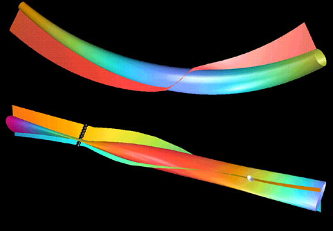
In the above image the top tensor icon was generated by
symmetric/antisymmetric decomposition of the tensor.
The symmetric tensor is visualized by a hyperstramline. The antisymmetric
tensor has only three independent components, which are encoded
in an additional vector field along the trajectory
of the hyperstreamline.
The bottom image was obtained by polar decomposition of a tensor.
The tensor is decomposed into a symmetric component representing a
stretch and an isometric transformation representing a rotation.
The symmetric tensor is again visualized as a hyperstreamline, whereas the
angle and axis of rotation of the second component define a surface
along the trajectory of the hyperstreamline.
The pearls in the image give the regions where the determinant of the
second tensor changes its sign.